Download
1 / 23
230 likes | 295 Views
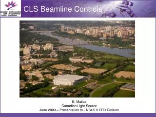
CLS Control System Contribution to System Reliability. Matias Canadian Light Source. Where is Saskatoon?. 1964 Saskatchewan Accelerator Lab (SAL) was established for chemistry and nuclear physics research.

E N D
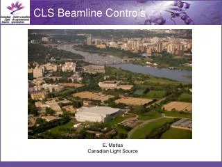
CLS Control System Contribution to System Reliability • Matias • Canadian Light Source
1964 Saskatchewan Accelerator Lab (SAL) was established for chemistry and nuclear physics research.
1964 Saskatchewan Accelerator Lab (SAL) was established for chemistry and nuclear physics research. • 1999 SAL operations were discontinued, and the accelerator was refurbished as an injector for a new storage ring. SR1 Machine Parameters 2.9 GeV DBA lattice with 12-fold period 170.88 m
Phase 1 (operation): Total of 7 scientific and 2 diagnostics beamlines. Phase 2 (commissioning): Total of 7 additional beamlines and building expansion for medical imaging. Phase 3 (pre-design): Total of 7 additional beamlines and building expansion.
Reliability • Two aspects to reliability: • Delivering quality reproducible beam • Delivering beam when scheduled without interruption (availability)
Approach to Reliability • EPICS Based control system • Highly distributed • Extensive use of PLC Equipment • Safety critical applications on a Safety Rated High Reliability PLC (IEC 61508) • Identify and remove “low reliability” components • Server Virtualization • High degree of Homogeneity • Problem Tracking • Structured ring-out process based on wiring diagrams, with as-builts and design packages • Human Factors
Homogeneity • Homogeneity (Oxford Dictionary)1 of the same kind. 2 consisting of parts all of the same kind. • An important principle in the design of the CLS control system and a contributor to reliability on several fronts
Homogeneity Advantages: • Reduced procurement cost (volume discounting). • Staff become familiar and experts in the equipment being used • reduced design, installation costs, • reduced human error. • Ability to manage spares inventory more effectively. • More effective management of legacy (discontinued) equipment. • Outside the accelerator community “The Southwest or WestJet advantage”.
Homogeneity Problems: • New staff like what they are use to from their previous lab. • Vendors of systems, would rather copy an existing design than use the lab standard. • You don’t always optimize every installation.
Reducing Mean Time to Repair • Master Drawing packages for each accelerator and beamline control system are stored in the control room • Process and Instrumentation Drawings Provide High-level overview of systems • Managing spares • Tagging failed modules
MKS Integrity • Problem Tracking System • Web based • Very useful in commissioning, especially with design staff working during the day and commissioning staff in the evening • Also used for “non-conformance” tracking of: • Internal/External QA audit items • Safety Items • Root-Cause-Analysis action items • We are now evaluating transitioning from MKS Integrity to a preventive maintenance and work order system
Design Package • A Design Package Includes: • PFD Drawings used by Mechanical Engineering to capture system layout and critical parameters, e.g., water flow rates etc. • P&ID Drawings used by Control to define the inputs and outs of the system and basic relationships • Partially based on American Instrumentation Society • Wiring diagrams • Requirements Document (later updated into the User Manual)
Human Factors HF bring these various activates together • Human Factors Workscope (Plan) • Incorporated user feedback (MKS) • Reduced complexity (standardization) • Task based support for operations (dash board) • Reduced cognitive memory recall (PID and associated screens) • Early stages of a systematic verification and validation against accepted industry HF standards