Download
1 / 76
1.1k likes | 2.35k Views
ELECTRONIC MATERIALS Lecture 10. SEMICONDUCTOR MATERIALS. Applied Electronics Department Technical University of Cluj-Napoca Cluj-Napoca, Cluj, 400027, Romania Phone: +40-264-401412, E-mail: cristian.farcas@ael.utcluj.ro.

E N D
ELECTRONIC MATERIALS Lecture 10 SEMICONDUCTOR MATERIALS Applied Electronics DepartmentTechnical University of Cluj-NapocaCluj-Napoca, Cluj, 400027, RomaniaPhone: +40-264-401412, E-mail: cristian.farcas@ael.utcluj.ro
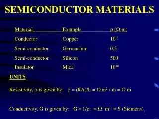
ELECTRONIC MATERIALS Lecture 10 According to their electrical conductivity, materials are conventionally classified into three groups: conductors, semiconductors and insulators. Conductors, which include all metals, have high conductivities, semiconductors show intermediate conductivities and insulators have low conductivities. The distinction between semiconductors and insulators is only quantitative, whereas the distinction between semiconductors and metals is more profound. All characteristic properties of semiconductors are the consequence of a basic physical phenomenon: the existence of certain energy bands in the energy spectrum of electrons. Semiconductor materials are insulators at absolute zero temperature that conduct electricity in a limited way at room temperature. The defining property of a semiconductor material is that it can be doped with impurities that alter its electronic properties in a controllable way.
ELECTRONIC MATERIALS Lecture 10
ELECTRONIC MATERIALS Lecture 10 Once we know the bandstructure of a given material we still need to find out which energy levels are occupied and whether specific bands are empty, partially filled or completely filled. Empty bands do not contain electrons. Therefore, they are not expected to contribute to the electrical conductivity of the material. Partially filled bands do contain electrons as well as available energy levels at slightly higher energies. These unoccupied energy levels enable carriers to gain energy when moving in an applied electric field. Electrons in a partially filled band therefore do contribute to the electrical conductivity of the material. Completely filled bands do contain plenty of electrons but do not contribute to the conductivity of the material. This is because the electrons cannot gain energy since all energy levels are already filled.
ELECTRONIC MATERIALS Lecture 10 Semiconductors differ from metals and insulators by the fact that they contain an "almost-empty" conduction band and an "almost-full" valence band. This also means that we will have to deal with the transport of carriers in both bands. To facilitate the discussion of the transport in the "almost-full" valence band of a semiconductor, we will introduce the concept of holes. It is important to understand that one could deal with only electrons if one is willing to keep track of all the electrons in the "almost-full" valence band. After all, electrons are the only real particles available in a semiconductor. The concepts of holes is introduced in semiconductors since it is easier to keep track of the missing electrons in an "almost-full" band, rather than keeping track of the actual electrons in that band. Holes are missing electrons. They behave as particles with the same properties as the electrons would have when occupying the same states except that they carry a positive charge.
ELECTRONIC MATERIALS Lecture 10
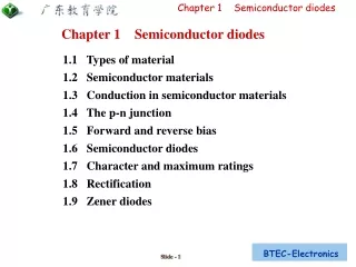
ELECTRONIC MATERIALS Lecture 10 CLASSIFICATION OF SEMICONDUCTORS Group III elemental semiconductors Boron (B) Group IV elemental semiconductors Diamond (C) Silicon (Si) Germanium (Ge) Tin (Sn) Group V elemental semiconductors Phosphorus (P) Arsenic (As) Antimony (Sb) Group VI elemental semiconductors Sulfur (S) Selenium (Se) Tellurium (Te) Group VII elemental semiconductors Iodine (I) Group IV compound semiconductors Silicon carbide (SiC) Silicon germanide (SiGe) III-V semiconductors Aluminium antimonide (AlSb) Aluminium arsenide (AlAs) Aluminium nitride (AlN) Aluminium phosphide (AlP) Boron nitride (BN) Boron arsenide (BAs) Gallium antimonide (GaSb) Gallium arsenide (GaAs) Gallium nitride (GaN) Gallium phosphide (GaP) Indium antimonide (InSb) Indium arsenide (InAs) Indium nitride (InN) Indium phosphide (InP)
ELECTRONIC MATERIALS Lecture 10 III-V quaternary semiconductor alloys Aluminium gallium indium phosphide (AlGaInP, also InAlGaP, InGaAlP, AlInGaP) Aluminium gallium arsenide phosphide (AlGaAsP) Indium gallium arsenide phosphide (InGaAsP) Aluminium indium arsenide phosphide (AlInAsP) Aluminium gallium arsenide nitride (AlGaAsN) Indium gallium arsenide nitride (InGaAsN) Indium aluminium arsenide nitride (InAlAsN) III-V quinary semiconductor alloys Gallium indium nitride arsenide antimonide (GaInNAsSb) III-V ternary semiconductor alloys Aluminium gallium arsenide (AlGaAs, AlxGa1-xAs) Indium gallium arsenide (InGaAs, InxGa1-xAs) Aluminium indium arsenide (AlInAs) Aluminium indium antimonide (AlInSb) Gallium arsenide nitride (GaAsN) Gallium arsenide phosphide (GaAsP) Aluminium gallium nitride (AlGaN) Aluminium gallium phosphide (AlGaP) Indium gallium nitride (InGaN) Indium arsenide antimonide (InAsSb) Indium gallium antimonide (InGaSb)
ELECTRONIC MATERIALS Lecture 10 I-VII semiconductors Cuprous chloride (CuCl) IV-VI semiconductors Lead selenide (PbSe) Lead sulfide (PbS) Lead telluride (PbTe) Tin sulfide (SnS) Tin telluride (SnTe) IV-VI ternary semiconductors lead tin telluride (PbSnTe) Thallium tin telluride (Tl2SnTe5) Thallium germanium telluride (Tl2GeTe5) II-VI semiconductors Cadmium selenide (CdSe) Cadmium sulfide (CdS) Cadmium telluride (CdTe) Zinc oxide (ZnO) Zinc selenide (ZnSe) Zinc sulfide (ZnS) Zinc telluride (ZnTe) II-VI ternary alloy semiconductors Cadmium zinc telluride (CdZnTe, CZT) Mercury cadmium telluride (HgCdTe) Mercury zinc telluride (HgZnTe) Mercury zinc selenide (HgZnSe)
ELECTRONIC MATERIALS Lecture 10 • There are two main types of semiconductor materials: • intrinsic - where the semiconducting properties of the material occur naturally i.e. they are intrinsic to the material's nature. • extrinsic - they semiconducting properties of the material are manufactured, by us, to make the material behave in the manner which we require. • Nearly all the semiconductors used in modern electronics are extrinsic. This means that they have been created by altering the electronic properties of the material. • Several different semiconducting materials exist, but the most common semiconductor material is Silicon and the two most common methods of modifying the electronic properties are: • Doping - the addition of 'foreign' atoms to the material. • Junction effects - the things that happen when we join differing materials together.
ELECTRONIC MATERIALS Lecture 10 Semiconductors' intrinsic electrical properties are very often permanently modified by introducing impurities, in a process known as doping. Usually it is reasonable to approximate that each impurity atom adds one electron or one "hole" that may flow freely. Upon the addition of a sufficiently large proportion of dopants, semiconductors conduct electricity nearly as well as metals. In addition to permanent modification through doping, the electrical properties of semiconductors are often dynamically modified by applying electric fields. The ability to control conductivity in small and well-defined regions of semiconductor material, statically through doping and dynamically through the application of electric fields (like transistors). Semiconductor devices with dynamically controlled conductivity are the building blocks of integrated circuits. In certain semiconductors, when electrons fall from the conduction band to the valence band (the energy levels above and below the band gap), they often emit light. This photoemission process underlies the light-emitting diode (LED) and the semiconductor laser, both of which are tremendously important commercially. Conversely, semiconductor absorption of light in photodetectors excites electrons from the valence band to the conduction band, facilitating reception of fiber optic communications, and providing the basis for energy from solar cells.
ELECTRONIC MATERIALS Lecture 10 GROWTH OF SEMICONDUCTOR CRYSTALS Like all crystals, semiconductor crystals can be obtained by cooling the molten semiconductor material. However, this procedure yields poly-crystalline material since crystals start growing in different locations with a different orientation. Instead when growing single-crystalline silicon one starts with a seed crystal and dips one end into the melt. By controlling the temperature difference between the seed crystal and the molten silicon, the seed crystal slowly grows. The result is a large single-crystal silicon boule. Such boules have a cylindrical shape, in part because the seed crystal is rotated during growth and in part because of the cylindrical shape of the crucible containing the melt. The boule is then cut into wafers with a diamond saw and further polished to yield the starting material for silicon device fabrication.
ELECTRONIC MATERIALS Lecture 10 This pure silicon ingot is about six inches across and a few feet long. When it's sliced, it will make thousands of silicon wafers, ready for processing. These wafers have been sawed from a solid ingot of silicon. Each wafer is six inches in diameter. One side of each wafer has already been polished smooth. Note the slight flat spot on the outside edge of each wafer to help hold it still during the polishing process.
ELECTRONIC MATERIALS Lecture 10 Polishing the Wafer Smooth Before the real work begins, one side of each wafer must be polished absolutely smooth. These wafers will be so smooth after they're finished that you couldn't detect any imperfections on the surface even with a microscope. The process is called chemical-mechanical polishing (CMP). As the name implies, it involves bathing the wafers in special abrasive chemicals and gently grinding any imperfections away. The wafers need to be smooth and flat because the features that will be projected onto them in the chip "darkroom" are extremely small and close together. In photography, it's important to keep the print lying flat as it develops because any warping or bending will throw the picture out of focus. Each part of the print must be the same distance from the projecting lens, and the principle is the same for chip making. Any variations in the surface of the silicon wafer will make the chip design out of focus, possibly causing shorts and other faults.
ELECTRONIC MATERIALS Lecture 10 Building the Layers After a wafer is polished, it's time to start building up the layers of material that will become the electronic components on the chip. A wafer is pure silicon, but it takes more than silicon to make a chip work. There are the metal wires, but those will be added later. At this stage, we need to build up a few layers of silicon (which conducts electricity) alternating with a few layers of an insulator (which doesn't conduct electricity). These two types of material will be stacked, like layers of frosting between layers of cake. Later, we'll etch away some of this insulator (most of it, actually), leaving a carefully planned-out three-dimensional pattern of silicon and other materials that channel electricity in exactly the paths we want. Engineers call this layering process deposition because chemicals are deposited on the supersmooth surface of our wafer. Deposition can be done in a couple of different ways. One way is to put the wafer in an oven along with pure oxygen gas and let the oxygen seep into the top of the wafer. (Oxygen doesn't conduct electricity; it is an insulator.) Another way is to spray the chemicals onto the wafer, called chemical vapor deposition (CVD). After we've built up the first layer of our chip, it will look like in figure.
ELECTRONIC MATERIALS Lecture 10 Layers of material are sprayed or deposited on top of the base silicon wafer. Alternating layers of conducting and insulating material are built up. The number of layers depends on the complexity of the chip. After each pair of conducting/insulating layers is put down, some of it is removed to make intricate wires.
ELECTRONIC MATERIALS Lecture 10 After we coat the wafer with insulating chemicals, there comes a second layer of special chemicals, this one called photoresist. Photoresist is like the coating on black-and-white print film before it's been developed. The stuff reacts to light, which we're depending on to make our chips work. Once the wafer is coated with photoresist, it's light sensitive and must be kept in the dark so that it doesn't accidentally get "developed" before it's ready. Fortunately for us, the photoresist is sensitive to light we can't see, so there's no need to shut off the lights in the clean room. The wafer still needs to be handled carefully, however, to avoid scratching its delicate and carefully prepared surface. To develop the wafer, we put it into a machine called a stepper. Usually a robot arm takes a wafer off the top of a stack and places it in the stepper automatically. Mounted just a few inches above the wafer is a copy of the film negative that the chip designers created (which was described in the previous chapter). Engineers call this film the reticle, and it's usually made of quartz instead of normal camera film. Just above the film is a lens and behind that is a bright light. Basically, we're going to project an image of the film down onto our wafer, like projecting slides onto a wall. The only real difference is the scale: The image we project will be tiny, only a fraction of an inch on a side, just big enough to make one copy of our chip.
ELECTRONIC MATERIALS Lecture 10 This wafer has been through several stages of the stepping and etching processes. The chips inscribed on it are clearly visible, making a grid pattern on the wafer's surface. Later, the wafer will be cut apart with a diamond-tipped saw, separating each of the square chips.
ELECTRONIC MATERIALS Lecture 10 These analog components, scattered across two silicon wafers, show the variety of shapes and sizes these components can take.
ELECTRONIC MATERIALS Lecture 10 ENERGY BAND DIAGRAMS OF SEMICONDUCTORS The energy band diagrams of semiconductors are rather complex. The detailed energy band diagrams of germanium, silicon and gallium arsenide are shown in the next figure. The energy is plotted as a function of the wavenumber, k, along the main crystallographic directions in the crystal, since the band diagram depends on the direction in the crystal. The energy band diagrams contain multiple completely-filled and completely-empty bands. In addition, there are multiple partially-filled band.
Energy band diagram of (a) germanium, (b) silicon and (c) gallium arsenide.
ELECTRONIC MATERIALS Lecture 10 The energy band diagrams are frequently simplified when analyzing semiconductor devices. Since the electronic properties of a semiconductor are dominated by the highest partially empty band and the lowest partially filled band, it is often sufficient to only consider those bands. This leads to a simplified energy band diagram for semiconductors as shown in the figure. The diagram identifies the almost-empty conduction band by a horizontal line. This line indicates the bottom edge of the conduction band and is labeled Ec. Similarly, the top of the valence band is indicated by a horizontal line labeled Ev. The energy band gap is located between the two lines, which are separated by the bandgap energy Eg.
ELECTRONIC MATERIALS Lecture 10 A simplified energy band diagram used to describe semiconductors. Shown are the valence and conduction band as indicated by the valence band edge, Ev, and the conduction band edge, Ec.
ELECTRONIC MATERIALS Lecture 10 TEMPERATURE DEPENDENCE OF THE ENERGY BANDGAP The energy bandgap of semiconductors tends to decrease as the temperature is increased. This behavior can be better understood if one considers that the interatomic spacing increases when the amplitude of the atomic vibrations increases due to the increased thermal energy. This effect is quantified by the linear expansion coefficient of a material. An increased interatomic spacing decreases the average potential seen by the electrons in the material, which in turn reduces the size of the energy bandgap. A direct modulation of the interatomic distance - such as by applying compressive (tensile) stress - also causes an increase (decrease) of the bandgap.
ELECTRONIC MATERIALS Lecture 10 The temperature dependence of the energy bandgap, Eg, has been experimentally determined yielding the following expression for Eg as a function of the temperature, T: where Eg(0), a and b are the fitting parameters. Parameters used to calculate the energy bandgap of germanium, silicon and gallium arsenide (GaAs) as a function of temperature are listed in the next table.
ELECTRONIC MATERIALS Lecture 10 Calculate the energy bandgap of germanium, silicon and gallium arsenide at 300, 400, 500 and 600 K.
ELECTRONIC MATERIALS Lecture 10 Solution: The bandgap of silicon at 300 K equals: Similarly one finds the energy bandgap for germanium and gallium arsenide, as well as at different temperatures, yielding:
ELECTRONIC MATERIALS Lecture 10 A plot of the resulting bandgap versus temperature is shown in the next figure for germanium, silicon and gallium arsenide. Temperature dependence of the energy bandgap of germanium (Ge), silicon (Si) and gallium arsenide (GaAs).
ELECTRONIC MATERIALS Lecture 10 INTRINSIC SEMICONDUCTOR An intrinsic semiconductor, also called an undoped semiconductor or i-type semiconductor, is a pure semiconductor without any significant dopant species present. The presence and type of charge carriers is therefore determined by the material itself instead of the impurities; the amount of electrons and holes is roughly equal. Intrinsic semiconductors conductivity can be due to crystal defects or to thermal excitation. In an intrinsic semiconductor the number of electrons in the conduction band is equal to the number of holes in the valence band. ni=pi A layer of i-type semiconductor is used in PIN diodes.
ELECTRONIC MATERIALS Lecture 10 PIN diode PIN diode (p-type, intrinsic, n-type diode) is a diode with a wide, undoped intrinsic semiconductor region between p-type semiconductor and n-type semiconductor regions. PIN diodes act as near perfect resistors at RF and microwave frequencies. The resistivity is dependent on the DC current applied to the diode. A PIN diode exhibits an increase in its electrical conductivity as a function of the intensity, wavelength, and modulation rate of the incident radiation. The benefit of a PIN diode is that the depletion region exists almost completely within the intrinsic region, which is a constant width (or almost constant) regardless of the reverse bias applied to the diode. This intrinsic region can be made large, increasing the area where electron-hole pairs can be generated. For these reasons many photodetector devices include at least one PIN diode in their construction, for example PIN photodiodes and phototransistors (in which the base-collector junction is a PIN diode). They are not limited in speed by the capacitance between n and p region anymore, but by the time the electrons need to drift across the undoped region.
ELECTRONIC MATERIALS Lecture 10 Conduction in Intrinsic Semiconductors A solid with filled bands is an insulator, but at finite temperature, electrons can be thermally excited from the valence band to the next highest, the conduction band. The fraction of electrons excited in this way depends on the temperature and the band gap, the energy difference between the two bands. Exciting these electrons into the conduction band leaves behind positively charged holes in the valence band, which can also conduct electricity. An intrinsic (pure) semiconductor's conductivity is strongly dependent on the band gap. The only available carriers for conduction are the electrons which have enough thermal energy to be excited across the band gap, which is defined as the energy level difference between the conduction band and the valence band.
ELECTRONIC MATERIALS Lecture 10 The band structure for intrinsic semiconductors. In intrinsic semiconductors (like silicon and germanium), the Fermi level is essentially halfway between the valence and conduction bands. Although no conduction occurs at 0K, at higher temperatures a finite number of electrons can reach the conduction band and provide some current.
ELECTRONIC MATERIALS Lecture 10 Conduction in Intrinsic Semiconductors Semiconductors are the class of elements which have four valence electrons. Two important semiconductors are germanium (Ge) and silicon (Si). Early solid-state electronic devices were fabricated almost exclusively from germanium, whereas modern devices are fabricated almost exclusively from silicon. Gallium arsenide (GaAs) is a semiconductor compound made up of gallium, which has three valence electrons, and arsenic, which has five. This semiconductor is making inroads in digital applications which require extremely high switching speeds and in extremely high-frequency analog applications. However, silicon remains the most useful semiconductor material and is expected to dominate for many years to come. Semiconductor materials are normally in crystalline form with each valence electron shared by two atoms. The semiconductor is said to be intrinsic if it is not contaminated with impurity atoms.
ELECTRONIC MATERIALS Lecture 10 Two-dimensional illustration of the crystal lattice of an intrinsic semiconductor at T=0K.
ELECTRONIC MATERIALS Lecture 10 The figure shows a two-dimensional view of an intrinsic semiconductor crystal. Each circle represents both the nucleus of an atom and all electrons in that atom except the valence electrons. The links between the circles represent the valence electrons. Each valence electron can be assumed to spend half time with each of two atoms so that each atom sees eight half-time electrons. Compared to a metal, the valence electrons in a semiconductor are tightly bound. The thermal energy stored in a semiconductor crystal lattice causes the atoms to be in constant mechanical vibration. At room temperature, the vibrations shake loose several valence electrons which then become free electrons. In intrinsic silicon, the number of free electrons is approximately one in 1012 of the total number of valence electrons. The free electrons behave similarly to those in a metal. Under the influence of an applied electric field, they have a mobility and exhibit a drift velocity which produces a conduction current. However, because of the small number of free electrons, the conductivity of an intrinsic semiconductor is much lower than that of a metal.
ELECTRONIC MATERIALS Lecture 10 When an electron is shaken loose from an atom, an electron vacancy is left which is called a hole. The parent atom then becomes an ion. The constant mechanical vibration of the lattice can cause the ion to capture a valence electron from a neighboring atom to replace the missing one. When such a transfer takes place, the position of the hole moves from one atom to another. This is equivalent to a positive charge +q moving about in the semiconductor. (The motion of a hole can be likened to the motion of a bubble in water.) Like free electrons, holes have a mobility and exhibit a drift velocity which produces a conduction current under the influence of an applied electric field. Because of the opposite charge polarity of electrons and holes, they drift in opposite directions under the influence of a field.
ELECTRONIC MATERIALS Lecture 10 Intrinsic semiconductor at T>0K.
ELECTRONIC MATERIALS Lecture 10 Next figure illustrates the drift of free electrons and the drift of holes in an intrinsic semiconductor under the application of an electric field that is directed from right to left for free electrons. When an electron is shaken loose from its valence shell, an electron-hole pair is formed. The force generated by the electric field causes the free electrons to drift to the left. In effect, a hole drifts to the right when a bound valence electron shifts to the left from one atom to another. The movement of holes may be likened to the movement of bubbles of air in water, where the water represents the bound electrons and the bubbles represent the holes. The movement of a bubble in one direction is really the result of a movement of water in the opposite direction. In summary, the flow of current in the semiconductor is the result of the flow of two components. One component is the flow of free electrons in one direction. The other component is the flow of the absence of bound electrons in the other direction. Because of the opposite charge polarities, the electron current and the hole current add to produce the total conduction current.
ELECTRONIC MATERIALS Lecture 10 Illustration of the drift of free electrons and the drift of holes under the application of an external electric field.
ELECTRONIC MATERIALS Lecture 10 Recombinations Because hole-electron pairs are continually created by thermal agitation of a semiconductor lattice, it might seem that the number of holes and free electrons would continually increase with time. This does not happen because free electrons are continually recombining with holes. At any temperature, a stable state is reached when the creation rate of hole-electron pairs is equal to the recombination rate. The mean lifetime τn(s) of a free electron is the average time that the electron exists in the free state before recombination. The mean lifetime τp(s) for the hole is defined similarly. In the intrinsic semiconductor, τn is equal to τp because the number of free electrons must be equal to the number of holes. However, the addition of an impurity to the semiconductor lattice can cause the mean lifetimes to be unequal.
ELECTRONIC MATERIALS Lecture 11 Conductivity This equation defines the conductivity σ of the intrinsic semiconductor. It is given by:
ELECTRONIC MATERIALS Lecture 11 Example 1 A rod of intrinsic silicon is 1 cm long and has a diameter of 1mm. At room temperature, the intrinsic concentration in the silicon is ni = 1.5 × 10¹⁶ per m3. The electron and hole mobilities are μe = 0.13m2 V−1 s−1 and μh = 0.05m2 V−1 s−1. Calculate the conductivity σ of the silicon and the resistance R of the rod.
ELECTRONIC MATERIALS Lecture 11 Solution. The conductivity is calculated as follows: The resistance is calculated as follows:
ELECTRONIC MATERIALS Lecture 11 EXTRINSIC SEMICONDUCTORS The preceding example illustrates how poor a conductor intrinsic silicon is at room temperature. The conductivity can be increased by adding certain impurities in carefully controlled minute quantities. When this is done, the semiconductor is called a doped semiconductor. There are two classes of impurities that are used. These are donor impurities and acceptor impurities. Typically one impurity atom is added per 108 semiconductor atoms. A semiconductor that is doped with a donor impurity is called an n-type semiconductor. One that is doped with an acceptor impurity is called a p-type semiconductor.
ELECTRONIC MATERIALS Lecture 11 n-Type Semiconductor An n-type semiconductor is produced by adding a donor impurity such as arsenic, antimony, or phosphorus to an intrinsic semiconductor. Each donor atom has five valence electrons. When a donor atom replaces an atom in the crystal lattice, only four valence electrons are shared with the surrounding atoms. The fifth valence electron becomes a free electron as illustrated in figure. The number of free electrons donated by the donor atoms is much greater than the number of free electrons and holes in the intrinsic semiconductor. This makes the conductivity of the n-type semiconductor much greater that of the intrinsic semiconductor. Because the number of free electrons is far greater than the number of holes, the free electrons are the majority carriers. The semiconductor is called n-type because the majority carriers have a negative charge.
ELECTRONIC MATERIALS Lecture 11 Two-dimensional illustration of the crystal lattice of an n-type semiconductor.
ELECTRONIC MATERIALS Lecture 11 Structure of energy bands of extrinsic semiconductors, doped with donor impurities.
ELECTRONIC MATERIALS Lecture 11 Hole-electron pairs are continually formed by thermal agitation of the lattice in an n-type semiconductor. Because of the large number of donor electrons, there are many more free electrons available for recombination with the holes. This decreases the mean lifetime for the holes which decreases the number of holes in the n-type semiconductor compared to the intrinsic semiconductor. For this reason, the current due to the flow of holes in an n-type semiconductor is often neglected in calculations. It is important to understand that a donor atom is electrically neutral if its fifth valence electron does not become a free electron in the lattice. If the fifth electron becomes a free electron, the number of protons in the atom is greater than the number of electrons by one. In this case, the donor atom becomes a bound positively charged ion.
ELECTRONIC MATERIALS Lecture 11 p-Type Semiconductor A p-type semiconductor is produced by adding an acceptor impurity such as gallium, boron, or indium to an intrinsic semiconductor. Each acceptor atom has three valence electrons. When an acceptor atom replaces an atom in the crystal lattice, there are only three valence electrons shared with the surrounding atoms. This leaves a hole as illustrated in next figure. The number of holes created by the acceptor atoms is much greater than the number of free electrons and holes in the intrinsic semiconductor. This makes the conductivity of the p-type semiconductor much greater that of the intrinsic semiconductor. Because the number of holes is far greater than the number of electrons, the holes are the majority carriers. The semiconductor is called p-type because the majority carriers have a positive charge.
ELECTRONIC MATERIALS Lecture 11 Two-dimensional illustration of the crystal lattice of a p-type semiconductor.