Download

1 / 36
360 likes | 444 Views
H. 323. Chapter 4. Definition. The H.323 standard provides a foundation for audio, video, and data communications across IP-based networks, including the Internet.

E N D
H. 323 Chapter 4
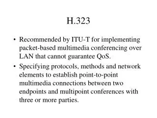
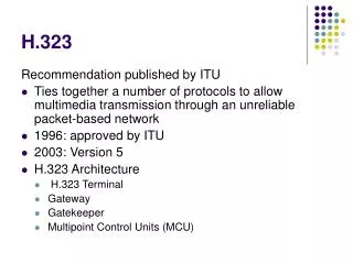
Definition • The H.323 standard provides a foundation for audio, video, and data communications across IP-based networks, including the Internet. • H.323 is an umbrella recommendation from the ITU that sets standards for multimedia communications over LAN’s that do not provide a guaranteed Quality of Service (QoS).
Why is it used • H.323 standards are important building blocks for a broad new range of collaborative, LAN-based applications for multimedia communications. • It includes parts of H.225.0 - RAS, Q.931, H.245 RTP/RTCP and audio/video codecs, such as the audio codec's (G.711, G.723.1, G.728, etc.) and video codec's (H.261, H.263) that compress and decompress media streams.
H323 is an umbrella • When dealing with H.323, it is good to realize that it is not a single protocol but rather an entire group of protocols. • The individual protocols used under the umbrella of H.323 include:
H.225.0 for call signalling; • Q.931, a protocol borrowed from ISDN, also used for call signalling; • H.245 for negotiating audio/video channel parameters; • H.235 for security and authentication; • RTP, the Real Time Protocol defined by IETF, used to transmit audio/video streams; • H.450.x for additional services like call transfer, call diversion, etc.
What Layer in OSI • Media streams are transported on RTP/RTCP. RTP carries the actual media and RTCP carries status and control information. • The signalling is transported reliably over TCP. • The following protocols deal with signalling:
H.323 Zone • H.323 defines several entity types that work together to form a “Zone”, all under the control of a single gatekeeper. • A Zone is the collection of all Terminals (Tx), Gateways (GW), and Multipoint Control Units (MCUs) managed by a single Gatekeeper (GK).
Zone • A Zone includes at least one terminal, and may or may not include Gateways or MCUs. A • Zone must have exactly one Gatekeeper. Otherwise a collection of entities is not considered a valid Zone, although that is not a requirement for operability.
Zone .... • A Zone may be independent of network topology and may be comprised of multiple network segments, which are connected using routers (R) or other devices. • See Figure for a sample Zone configuration.
Terminals and Gateways Terminal • Terminals are single endpoints used to communicate through the transmission of information streams, as specified in H.323. Gateway • In general, the purpose of the Gateway is to interface between a packet-based network endpoint to a traditional switched circuit network (SCN) endpoint, and the reverse, in a transparent fashion. • The Gateway provides the appropriate translation between transmission formats and between communications procedures
Gatekeeper • The Gatekeeper provides call control services to the H.323 endpoints. • More than one Gatekeeper may be present and communicate with each other in an unspecified fashion. • The Gatekeeper is logically separate from the endpoints; however, its physical implementation may coexist with a terminal, MCU Gateway, or other device.
Gatekeeper functions • Address translation - The Gatekeeper translates between alias address to transport address. • Admissions control - The Gatekeeper authorizes network access. • Bandwidth control - The Gatekeeper performs bandwidth control for bandwidth requests. • Zone management - The Gatekeeper provides the above functions for terminals, • MCUs, and Gateways, which have registered with it.
Other Gatekeeper services • Call control signalling - The Gatekeeper may choose to complete the call signalling with the endpoints, and may process the call signalling itself. • Alternatively, the Gatekeeper may direct the endpoints to connect the Call Signalling Channel directly to each other • Call authorization - The Gatekeeper may reject calls due to authorization failure. • Bandwidth management - The Gatekeeper may reject calls from a terminal due to bandwidth management criteria. • Call management - The Gatekeeper may maintain call status for endpoints. • Directory services - The Gatekeeper may provide some directory information to route calls.
Multipoint Control Unit (MCU) • The MCU is an endpoint, which provides support for multipoint conferences • If several users are on stream the MCU controls conferencing between them
1. The endpoint that initiates the call knows the called number (122) but it does not know the IP address associated with that number. At the same time, since it is registered with the gatekeeper, it must ask the gatekeeper for a permission to place the call. It does so by sending the Admission Request message to the gatekeeper. The Admission Request (ARQ) will contain the called number (122), indicating to the gatekeeper that the endpoint needs to have the number resolved to an IP address.
2. The gatekeeper will check it's database of registered endpoints whether it contains the number 122. If so, the gatekeeper will check if 121 is allowed to call 122 and if it is possible to place the call — for example, if there is enough bandwidth (a bandwidth limit could be configured on the gatekeeper for a subnet that's connected via some WAN link). After that, the gatekeeper will form an answer — the message Admission Confirm (ACF) with an IP address and send the ACF to the calling endpoint.
3. The endpoint 121 will now open a call signalling channel to the address provided by the gatekeeper in the ACF message. The call signalling messages are sent over TCP and the protocol is H.225.0, embedded in Q.931 (we will denote this as Q.931/H.225.0). With the gatekeeper-routed call model, the endpoint 121 will open a TCP channel to the gatekeeper and send the Q.931/H.225.0 message Setup. The gatekeeper will in turn open a second TCP channel to the endpoint 122 and forward the Setup message.
4. The endpoint 122 will first respond with the Q.931/H.225.0 message Call Proceeding to indicate it has started working on setting up the call and the gatekeeper will forward the message to the calling endpoint. After that, 122 will ask the gatekeeper for a call permission (Admission Request, ARQ) and the gatekeeper will respond with Admission Confirm (ACF).
5. The called telephone (122) starts ringing and this is signalled to the other party with the Q.931/H.225.0 message Alerting. 6. The called party picks up the handset and the endpoint can signal the call has been accepted. This is done by sending the Q.931/H.225.0 message Connect. At this point, the parties will need to negotiate parameters for audio (and optionally video) channels. The protocol H.245 is used for this negotiation.
7. The calling endpoint opens a TCP channel to the H.245 address it has received in the Connect message, and the gatekeeper will establish the second "half" of the H.245 signalling channel. The endpoints can start exchanging H.245 messages. The H.245 negotiation has three parts: Deciding which endpoint is the "master" and which is the "slave". Exchanging information about the capability set of each party. Deciding what codec’s will be used
8. Finally, the two endpoints can start sending the RTP streams and the two people will hear one another. Note that each of the two directions can be encoded with a different codec.
When the call is over ... • The two endpoints stop sending the RTP streams. • They announce the closing of logical channels (H.245 RequestCloseLogicalChannel). • The H.245 signalling channel is closed (H.245 command message EndSessionCommand followed by closing of the TCP connection).
The main signalling connection is also closed — the endpoints exchange Q.931/H.225.0 messages ReleaseComplete and the TCP connection is closed.Each of the two endpoints informs the gatekeeper about the completed call with the H.225.0-RAS message Disengage Request (DRQ) and the gatekeeper confirms with Disengage Confirm (DCF).