Download
1 / 34
340 likes | 491 Views
Direct-current Circuits. PHY232 – Spring 2008 Jon Pumplin http://www.pa.msu.edu/~pumplin/PHY232 (Original ppt courtesy of Remco Zegers). So far, we have looked at systems with only one resistor.

E N D
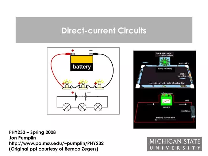
Direct-current Circuits PHY232 – Spring 2008 Jon Pumplin http://www.pa.msu.edu/~pumplin/PHY232 (Original ppt courtesy of Remco Zegers)
So far, we have looked at systems with only one resistor Now look at systems with multiple resistors, which are placed in series, parallel or in series and parallel. for “ohmic” resistor: PHY232 - Spring 2008 - Direct Current Circuits
quiz • At V=10V someone measures a current of 1A through the below circuit. When she raises the voltage to 25V, the current becomes 2 A. Is the resistor Ohmic? a) YES b) NO PHY232 - Spring 2008 - Direct Current Circuits
building blocks battery or other potential source: Provides emf (electromotive force) to the circuit switch: allows current to flow is closed ampere meter: measures current volt meter: measures voltage resistor capacitance lightbulb (I usually show a realistic picture or resistor instead) PHY232 - Spring 2008 - Direct Current Circuits
light bulb • made of tungsten: =4.8x10⁻³ 1/K • temperature of filament: ~2800 K • so R=R0[1+(T-T0)]=13R0 !!! • consequences: • A hot lightbulb has a much higher resistance • A light bulb usually fails just when switched on because the resistance is small and the current high, and thus the power delivered high (P=I2R) • In the demos shown in this lecture, all lightbulbs have the same resistance if at the same temperature, but depending on the current through them, the temperature will be different and thus their resistances PHY232 - Spring 2008 - Direct Current Circuits
assumptions I • 1) The internal resistance of a battery or other voltage source is zero. This is not really true (notice that a battery becomes warm after being used for a while) • if this were not the case a system like this: • should be replaced with I V I internal resistance V Vinternal=IRinternal PHY232 - Spring 2008 - Direct Current Circuits
assumptions II 1 • An ampere meter (current meter) has a negligible internal resistance, so that the voltage drop over the meter VA=IRA is negligible as well • usually, we do not even draw the ampere meter even though we try to find the current through a certain line • remember that an ampere meter must be placed in series with the device we want to measure the current through A B PHY232 - Spring 2008 - Direct Current Circuits
question 1 A B 10V • If in the above circuit the resistance of the Ampere meter • is not zero, it will not measure the right current that would • be present if the meter were not present. • true, the total current will change and thus also the current • in the Ampere meter • b) not true, current cannot get stuck in the line and thus the • measurement will not be affected PHY232 - Spring 2008 - Direct Current Circuits
assumptions III 1 • a volt meter has an infinite internal resistance, so that no current will flow through it. • usually, we do not even draw the volt meter even though we try the potential over a certain branch in the circuit • remember that a volt meter must be placed in parallel with the device we want to measure the voltage over A B PHY232 - Spring 2008 - Direct Current Circuits
assumptions IV • We can neglect the resistance of wires that connect the various devices in our circuit. This is true as long as the resistance of the device is much larger than that of the wires PHY232 - Spring 2008 - Direct Current Circuits
basic building blocks: two resistors in series Poiseuille: Flow~Pr4/l • The water flow (m3/s) through the two narrow pipes must be equal (else water gets stuck), so the pressure drop is larger over the narrowest of the two. The total pressure drop is equal to the sum of the two pressure drops over both narrow pipes • The current (I) through the two resistors must be equal (else electrons would get stuck), so the voltage drop is larger over the highest of the two. The total voltage drop is equal to the sum of the two voltage drops over the resistors. 1m wide 2m wide PHY232 - Spring 2008 - Direct Current Circuits
demo 2 light in series resistors in series II The voltage over R1 and R2: 1) if we want to replace R1,R2 with one equivalent R: 2) and by combining 1) and 2) • For n resistors placed in series in a circuit: Req = R1+R2+…+Rn Note: Req>Ri I=1,2…n the equivalent R is always larger than each of the separate resistors I R2 R1 V PHY232 - Spring 2008 - Direct Current Circuits
second building block: resistors in parallel 1m wide 1.5m wide • The pressure drop over the two narrow pipes must be equal (before and after the pipes the pressure is the same), but the water prefers to flow through the wider canal, i.e, the flow (m3/s) is higher through the wider canal. • The voltage drop over the two resistors must be equal (before and after the resistors the voltage is the same), but the electrons prefer to go through the smaller resistor, i.e, the current (A) is higher through the smaller resistor. PHY232 - Spring 2008 - Direct Current Circuits
demo 2 light in parallel resistors in parallel II I2 R2 For the current through the circuit: 1) if we want to replace R1,R2 with one equivalent R: 2) and by combining 1) and 2): • For n resistors placed in parallel in a circuit: 1/Req = 1/R1+1/R2+…+1/Rn Note: Req<Ri with I=1,2…n Req is always smaller than each of the separate resistors I1 R1 I V PHY232 - Spring 2008 - Direct Current Circuits
question • what is the equivalent resistance of all resistors as placed in the below circuit? If V=12V, what is the current I? R3 R1=3 Ohm R2=3 Ohm R3=3 Ohm V=12V R2 R1 I V R2 & R3 are in parallel 1/R23=1/R2+1/R3=1/3+1/3=2/3 R23=3/2 Ohm R1 is in series with R23 R123=R1+R23=3+3/2=9/2 Ohm I=V/R=12/(9/2)=24/9=8/3 A PHY232 - Spring 2008 - Direct Current Circuits
question: Christmas tree lights • A tree is decorated with a string of many equal lights placed in parallel. If one burns out (no current flow through it), what happens to the others? a) They all stop shining b) the others get a bit dimmer c) the others get a bit brighter d) the brightness of the others remains the same R R I V PHY232 - Spring 2008 - Direct Current Circuits
question: Christmas tree lights • A tree is decorated with a string of many equal lights placed in parallel. If one burns out (no current flow through it), what happens to the others? • a) They all stop shining • b) the others get a bit dimmer • c) the others get a bit brighter • d) the brightness of the others remains the same Before the one light fails: 1/Req=1/R1+1/R2+…+1/Rn if there are 3 lights of 1 Ohm: Req=1/3 I=V/ReqIj=V/Rj (if 3 lights: I=3V Ij=V/1 After one fails: 1/Req=1/R1+1/R2+….+1/Rn-1 if there are 2 lights left: Req=1/2 I=V/ReqIj=V/Rj(if 2 lights: I=2V Ij=V/1) The total resistance increases, so the current drops. The two effects cancel each other R R I V PHY232 - Spring 2008 - Direct Current Circuits
Assume: If one fails, the wire inside it is broken and Current cannot flow through it any more. A different Christmas tree • a person designs a new string of lights which are placed in series. One fails, what happens to the others? • a) They all stop shining • b) the others get a bit dimmer • c) the others get a bit brighter • d) the brightness of the others remains the same PHY232 - Spring 2008 - Direct Current Circuits
Kirchhoff’s rules • To solve complex circuits, we can use the following rules: • Kirchhof 1: The sum of the currents flowing into a junction must be the same the the sum of the current flowing out of the junction. • Kirchhof 2: The sum of voltage gains over a loop (I.e. due to emfs) must be equal to the sum of voltage drops over the loop. I3 I1 I4 I1+I2+I3=I4+I5 I2 I5 I R2 R1 I=IR1+IR2 PHY232 - Spring 2008 - Direct Current Circuits
question • Given V=12V, what is the current through and voltage over each resistor • 1) Slide 12: I1=8/3 A • Kirchhof 2 • 2) V-I1R1-I2R2=0 12-3I1-3I2=0 • Kirchhof 2 • 3) V-I1R1-I3R3=0 12-3I1-3I3=0 • Kirchhof 2 • 4) 0-I3R3+I2R2=0 -3I3+3I2=0 • Kirchhoff I • 5) I1-I2-I3=0 I1=I2+I3 • & 2) 12-8-3I2=0 so 4=3I2 and I2=4/3 A • 1) & 3) 12-8-3I3=0 so 4=3I3 and I3=4/3 A • Use V=IR for R1 V1=8/3*3=8 V • for R2 V2=4/3*3=4 V • for R3 V3=4/3*3=4 V I3 R3 I1 R1=3 Ohm R2=3 Ohm R3=3 Ohm V=12V R2 R1 I2 I=I1 I=I1 V demo lightbulb circuit PHY232 - Spring 2008 - Direct Current Circuits
IMPORTANT • When starting a problem we have to assume something about the direction of the currents through each line. It doesn’t matter what you choose, as long as you are consistent throughout the problem example: I3 R3 I3 R3 I1 I1 both are okay R2 R2 R1 R1 I2 I2 I=I1 I=I1 I=I1 I=I1 V V Kirchhoff I: I1+I2+I3=0 Kirchhoff I: I1-I2-I3=0 Kirchhoff 2: V-I1R1-I2R2=0 Kirchhoff 2: V-I1R1+I2R2=0 PHY232 - Spring 2008 - Direct Current Circuits
NOT A LOOP question • which of the following cannot be correct? • a) V-I1R1-I3R3-I2R2=0 • b) I1-I3-I4=0 • c) I3R3-I6R6-I4R4=0 • d) I1R1-I3R3-I6R6-I4R4=0 • e) I3+I6+I2=0 I1,R1 I4 R4 V I3 R3 I6 R6 I2 R2 I5 R5 PHY232 - Spring 2008 - Direct Current Circuits
question R4 I4 • What is Kirchhoff I for ? • I1+I2-I3-I4=0 b) I1+I2+I3+I4=0 c) I1-I2-I3-I4=0 • What is Kirchhoff II for the left small loop • ( with R4 and R1?) • a) I4R4+I1R1=0 b) I4R4-I1R1=0 c) I4R4+I1R1-V=0 I3 R3 What is Kirchhoff II for the right small loop (with R2 and R3)? • I3R3+I2R2=0 b) I3R3-I2R2=0 c) I3R3-I2R2+V=0 What is Kirchhoff II for the loop (with V,R4 and R3)? a) V-I4R4+I3R3=0 b) V+I4R4-I3R3=0 c) V-I4R4-I3R3=0 R2 R1 I1 I2 V PHY232 - Spring 2008 - Direct Current Circuits
question • what is the power dissipated by R3? P=VI=V2/R=I2R I3 R3 I1 I4 R4 R1= 1 Ohm R2=2 Ohm R3=3 Ohm R4=4 Ohm V=5V R2 R1 I2 I=I1 I=I1 V We need to know V3 and/or I3. Find equivalent R of whole circuit. 1/R23=1/R2+1/R3=1/2+1/3=5/6 R23=6/5 Ohm R1234=R1+R23+R4=1+6/5+4=31/5 Ohm I=I1=I4=V/R1234=5/(31/5) I=25/31 A Kirchhoff 1: I1=I2+I3=25/31Kirchhoff 2: I3R3-I2R2=0 so 3I3-2I2=0 I2=3/2 I3 Combine: 3/2 I3+I3=25/31 so 5/2 I3=25/31 I3=10/31 A P=I2R so P=(10/31)2*3=(100/961)*3=0.31 J/s PHY232 - Spring 2008 - Direct Current Circuits
more than one emf I1 I3 what is the current through and voltage over each R? R1=R2=R3=3 Ohm V1=V2=12 V • apply kirchhoff’s rules 1) I1+I2-I3=0 (kirchhoff I) 2) left loop: V1-I1R1+I2R2=0 so 12-3I1+3I2=0 3) right loop: V2+I3R3+I2R2=0 so 12+3I3+3I2=0 4) outside loop: V1-I1R1-I3R3-V2=0 so –3I1-3I3=0 so I1=-I3 combine 1) and 4) I2=2I3 and put into 3) 12+9I3=0 so I3=4/3 A and I1=-4/3 A and I2=8/3 A R1 R3 R2 I2 V1 V2 PHY232 - Spring 2008 - Direct Current Circuits
1 3 2 circuit 1: I=12/(2R)=6/R VA=12-6/R*R=6V circuit 2: VB=12V circuit 3: I=12/(3R)=4/R VC=12-4/R*R=8V VD=12-4/R*R-4/R*R=4V question A B C D 12V 12V 12V At which point (A,B,C,D) is the potential highest and at which point lowest? All resistors are equal. • highest B, lowest A • highest C, lowest D • highest B, lowest D • highest C, lowest A • highest A, lowest B PHY232 - Spring 2008 - Direct Current Circuits
circuit breakers Circuit breakers are designed to cut off power if the current becomes too high. In a house a circuit breaker is rates at 15A and is connected to a line that holds a coffee maker (1200 W) and a toaster (1800 W). If the voltage is 120 V, will the breaker cut off power? P=VI 1800+1200=120 x I I=3000/120=25 A 25A>15 A the breaker will cut off power PHY232 - Spring 2008 - Direct Current Circuits
Question: R3 R2 R1 • consider the circuit. Which of the following is/are not true? • If R2=R3=2R1 the potential drops over R1 and R2 are the same • for any value of R1,R2 and R3 the potential drop over R1 must be equal to the potential drop over R2 • The current through R1 is equal to the current through R2 plus the current through R3 (I1=I2+I3) I V • 1 is not true • 2 is not true • 3 is not true • 1&2 are not true • 1&3 are not true PHY232 - Spring 2008 - Direct Current Circuits
if R2=R3=2R1 then 1/R23=1/R2+1/R3=1/R1 so R23=R1 and I1=I23 and potential of R1 equals the potential over R23 and thus R2 and R3. THIS IS TRUE • no, this is only TRUE in the case of 1) • true: conservation of current. answer R3 R2 R1 • consider the circuit. Which of the following is/are not true? • If R2=R3=2R1 the potential drops over R1 and R2 are the same • for any value of R1,R2 and R3 the potential drop over R1 must be equal to the potential drop over R2 • The current through R1 is equal to the current through R2 plus the current through R3 (I1=I2+I3) I V • 1 is not true • 2 is not true • 3 is not true • 1&2 are not true • 1&3 are not true PHY232 - Spring 2008 - Direct Current Circuits
RC circuits Consider the below circuit. • When the battery is connected, a current passes through the resistor, and the capacitor begins to charge up. • As the capacitor gets more charge, and hence more voltage, the voltage across the resistor decreases, so the current decreases. • Eventually, the capacitor becomes essentially fully charged, so the current becomes essentially zero. • The maximum charge is given by Q=CV V PHY232 - Spring 2008 - Direct Current Circuits
RC circuit II for the charge on the capacitor for the voltage over the capacitor for the voltage over the resistor for the current e = 2.718… PHY232 - Spring 2008 - Direct Current Circuits
Voltage switched on RC time voltage switched off • The value is the time constant. It is the time it takes to increase the stored charge on the capacitor to ~63% of its maximum value (1/e=0.63) PHY232 - Spring 2008 - Direct Current Circuits
a) if (1-e-t/RC)=0.75 then charged for 75%, so e-t/RC=0.25 t/RC=-ln(0.25) ln: natural logarithm t=-RC x ln(0.25)=-100x10-5x(-1.39)= 1.39x10⁻³ seconds. b) maximum current: at t=0 it is as if the capacitor C is not present so I=V/R=0.1 A question • given: V=10 V R=100 Ohm C=10x10-6 F V The emf source is switched on at t=0. a) After how much time is the capacitor C charged to 75% of its full capacity? b) what is the maximum current through the system? PHY232 - Spring 2008 - Direct Current Circuits
warning • there is a question in lon-capa that looks like an RC question, but the current is constant… be careful. PHY232 - Spring 2008 - Direct Current Circuits