Download
1 / 13
130 likes | 272 Views
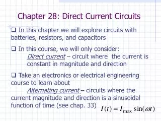
Direct Current Circuits. A current is maintained in a closed circuit by an emf (electromotive force) Battery. An emf forces electrons to move against the electrostatic field in the source. It is the work done per unit charge in volts.

E N D
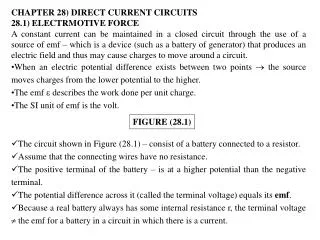
Direct Current Circuits • A current is maintained in a closed circuit by an emf (electromotive force) Battery. • An emf forces electrons to move against the electrostatic field in the source. It is the work done per unit charge in volts. • Neglecting resistance within a battery the potential difference across the terminals is the emf of the battery.
Resistance in a battery • Let E = emf, I = the current that flows, r the resistance in a battery. • As a charge is moved through a battery against the field (doing work on the charge) the potential difference is increased by E-Ir • If the current was zero E = terminal voltage called open circuit voltage.
Battery resistance cont. • Placing a resistor in the circuit R (load resistance) E = IR + Ir I = E/(R+r). However if R is much greater than r then r is neglected. • Power output from a source P = IE = I2R
Resistors in Series • A resistor can be anything that resists the flow of the current. Ex. Light bulb, heater. • If two or more resistors are in a circuit one after the other the current that flows through one is the same as that flowing through the other. The sum of the potential difference (V) across the resistors = the total potential difference across the combination • V = IR1+ IR2 = I(R1+ R2) =IReq, Req = R1+ R2
Resistors in Parallel • For resistors in parallel, R1 and R2 the potential difference across them is the same as they are both connected the same to the source. When a current comes to the junction of a connection it will split ( I = I1+I2) and more current will flow through the area of less resistance. The equivalent resistance is given by 1/Req = 1/R1 + 1/R2
Series vs Parallel • Systems in parallel operate independently. If one resistor is removed the others will continue to operate. In series if one is inoperative all will be inoperative. • Household wiring is done in parallel so items operate independently. Circuit breakers are in series to control maximum current flow to prevent overheating of wires
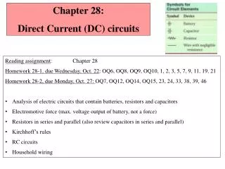
Kirchhoff’s Rules and Complex DC Circuits • 1) The sum of currents entering any junction must equal the sum of the currents that leave that junction ( Junction Rule) Conservation of charge no build up or loss • 2) The sum of the potential differences across all the elements around any closed circuit loop must be zero. (Loop rule ) Conservation of energy a charge that moves through a closed circuit will gain what it losses. Gain from the emf source
Kirchhoff cont. • When applying the rules make the following decisions. • 1) Assign symbols and directions to all branches of a circuit • 2) When applying the loop rule choose a direction to travel the loop. Record voltage drops and rises according to the following rules.
Cont. • A)Traversing a resistor in the direction of the current, the change in electric potential across the resistor is -IR • b) Traversing a resistor in the direction opposite the current, the change in electric potential across the resistor is +IR.
Cont. • C)If emf source is traversed in the direction of the emf, from - to + , the change in electric potential is + E • D)If the emf source is traversed opposite the direction of the source + to - the change in electric potential is - E • The junction rule can only be used up to one time less than the number of junctions in a circuit.
Cont. • The loop rule can be used as often as needed as long as a new circuit element (resistor or battery) or a new circuit appears in each equation. • To solve a particular circuit problem, you need as many independent equation as there are unknowns. • Study examples on p 603 and 604
RC Circuits • An RC circuit contains at least a resistor and a capacitor. • When the switch is initially closed the battery’s current passing through the resistor starts to charge the capacitor. The current constantly changes until the capacitor reaches maximum charge Q = CE, where E is the max voltage across the capacitor. At max charge the current ceases to flow. Charge on the capacitor varies with time by the following q = Q(1-e-t/RC) where e = 2.718 Euler’s constant
RC cont. • The voltage across the capacitor at any time is V= q/C • The term RC in the above equation is the Time Constant = т (tau) which the time required to reach 63.2% of charge = .632Q • After 10 time constants the capacitor is considered 99.99% charged.