Download
1 / 45
460 likes | 583 Views
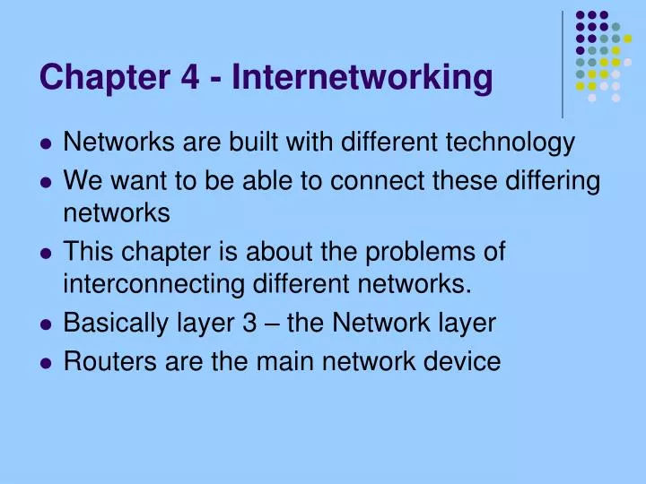
Chapter 4 - Internetworking. Networks are built with different technology We want to be able to connect these differing networks This chapter is about the problems of interconnecting different networks. Basically layer 3 – the Network layer Routers are the main network device. Main Issues.

E N D
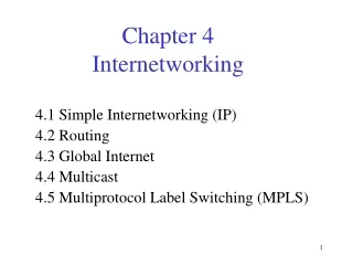
Chapter 4 - Internetworking • Networks are built with different technology • We want to be able to connect these differing networks • This chapter is about the problems of interconnecting different networks. • Basically layer 3 – the Network layer • Routers are the main network device
Main Issues • IP or Internet protocol • Finding efficient, loop-free paths through the constituent networks • Internet problems: address space, large routing tables, scaleable networks • Multicast
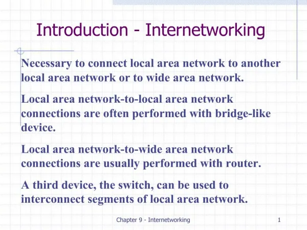
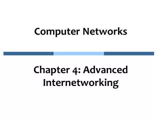
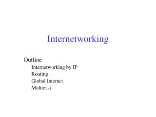
What is an Internetwork? • Look over figures 4.1and 4.2 • They are graphically describing the issue of interconnecting differing networks and a simple way of looking at the overall changing of protocols • IP service model: best effort
Network 1 (Ethernet) H7 R3 H8 H2 H1 H3 Network 4 (point-to-point) Network 2 (Ethernet) R1 R2 H4 Network 3 (FDDI) H5 H6
H1 H8 TCP TCP R1 R2 R3 IP IP IP IP IP FDDI PPP ETH ETH ETH FDDI PPP ETH
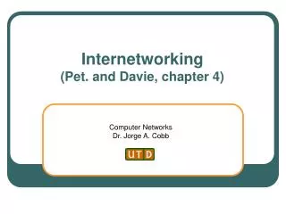
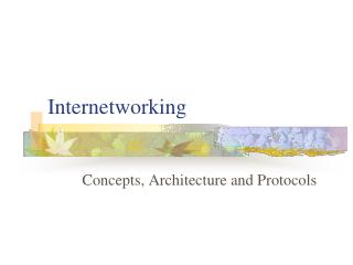
IP Packet Structure • Note in particular: • source address • destination address • TTL (time-to-live) • Protocol (higher level-TCP, UDP etc.)
0 4 8 16 19 31 TOS Length V ersion HLen Ident Flags Offset TTL Protocol Checksum SourceAddr DestinationAddr Pad Options (variable) (variable) Data
IP Addresses • Examples: • www.cnn.com 64.236.16.20 • Registered to billionaire Ted Turner, one big site!! • www.nvc.cs.vt.edu 208.22.18.79 • CS department site, a small to medium site • www.somuchdata.com hosted at 216.40.247.57 • Registered to me, William May (used to advertise a book I wrote three years ago), a very small site!
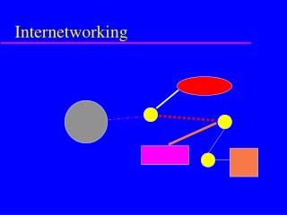
IP Addresses and Classes • Class A, B and C addresses • Shown in figure 4.6 • For most medium to large organizations like companies, universities, government offices etc. Class A is way too big and Class C is too small • Class B is where the crunch came
7 24 (a) 0 Network Host 14 16 (b) 1 0 Network Host 21 8 (c) 1 1 0 Network Host
Datagram forwarding in IP • Every IP datagram contains the destination IP address • The “network” part of the address uniquely identifies a single physical network • All hosts that share the same network part of the address, are connected to the same physical network and can communicate with each other by sending frames over that network
So just how does the datagram get forwarded? • Two parts • Routers forward the datagram based on the network part of the address • At the end there has to be a (local) table of address pairs – that is a table that maps IP addresses into physical addresses • ARP (Address Resolution Protocol)
And how does a sender determine where to send the datagram? • A host needs the address of the first router to send a datagram on its way • Called the default router • DHCP is one common way of learning which is your default router
Unicast to server DHCP DHCP Other networks relay server Broadcast Host
Virtual Networks and Tunnels • Figure 4.12 explains it best, another level of encapsulation
Internetwork R2 Network 2 Network 1 R1 10.0.0.1 IP header , IP header , IP header , Destination = 2.x Destination = 10.0.0.1 Destination = 2.x IP header , IP payload IP payload Destination = 2.x IP payload
Routing • Routing table – generally contains mappings from network numbers to next hops (which are labeled as output ports on the router) • “Routing is the process by which forwarding tables are built.” (page 281)
Routing Protocols • Routers talking to other routers • (very roughly-experts would shoot me for this analogy!) the router analog of the spanning tree procedure for switches
Routing Protocols • We will look at several: • Static routes (work fine for small internetworks) • RIP (most widely used, simple but can be used on reasonably large internetworks) • OSPF (scaleable, good for campus-sized internetworks) • BGP (used by ISPs, very complicated, we will only discuss in passing)
RIP • The ICND book has a great presentation of this protocol • I recommend going over that presentation, it is mainly pictures of how the routing table changes • Distance vector – RIP counts “hops”
1 4 A B 2 5 C D 3 6
OSPF • Link State • Figure 4.17 (next slide) show the basics of how the routers talk to each other
X A X A C B D C B D (a) (b) X A X A C B D C B D (c) (d)
B 3 5 10 C A 11 2 D
OSPF Hierarchy • Hierarchy is one of the main tools to make systems more scaleable • OSPF allows more hierarchy to be imposed by partitioning a domain into areas • This means: a router within a domain does not necessarily need to know how to reach every network within that domain – cuts down on the information that has to be stored and processed
Area 3 Area 1 Area 0 R9 R7 R3 R8 R1 R4 R2 Area 2 R6 R5
0 8 16 31 V ersion T ype Message length SourceAddr AreaId Checksum Authentication type Authentication
LS Age Options T ype=1 Link state ID Advertising router LS sequence number LS checksum Length 0 Flags 0 Number of links Link ID Link data Link type Num_TOS Metric Optional TOS information More links
The Internet • 1990 form in figure 4.23 • Today’s is shown next
Large corporation “ ” Consumer ISP Peering point Backbone service provider Peering point Consumer ” ISP “ “ Consumer ” ISP Large corporation Small corporation
Exhaustion of IP Addresses • ~4,000,000,000 (232 addresses) are not enough! • Class B particularly bad off • Subnetting and CIDR (Classless InterDomain Routing) are a temporary solution
Network number Host number Class B address 111111111111111111111111 00000000 Subnet mask (255.255.255.0) Network number Subnet ID Host ID Subnetted address
Subnet mask: 255.255.255.128 Subnet number: 128.96.34.0 128.96.34.15 128.96.34.1 H1 R1 Subnet mask: 255.255.255.128 128.96.34.130 Subnet number: 128.96.34.128 128.96.34.139 128.96.34.129 H2 R2 H3 128.96.33.1 128.96.33.14 Subnet mask: 255.255.255.0 Subnet number: 128.96.33.0
BGP • Additional level of hierarchy: AS or Autonomous Systems • Page 322 explains three major problems with interdomain routing and the Internet. • BGP is designed to help with these • A very hard protocol, the book only skims over it
Corporation X (11000000000001000001) Border gateway Regional network (advertises path to 11000000000001) Corporation Y (11000000000001000000)
128.96 Customer P 192.4.153 (AS 4) Regional provider A (AS 2) Customer Q 192.4.32 (AS 5) 192.4.3 Backbone network (AS 1) Customer R 192.12.69 (AS 6) Regional provider B (AS 3) Customer S 192.4.54 (AS 7) 192.4.23
IPv6 • Aimed at solving several of the problems that we have seen • The book describes the packet at a high level but doesn’t focus on what IPv6 will do for the Internet of the future
Multicast • Motivation: there are applications that want to send a packet to more than one destination host • Forcing the source to send a separate packet to each destination host wastes resources big time! • Multicast (a work still in progress) is aimed at making this procedure more efficient by not forcing separate packets on the sender
B R1 R2 A R3 R4 R5 C R6 R7