Download
1 / 26
260 likes | 265 Views
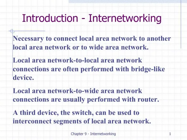
Chapter 1: Internetworking. Internetworking Basics Network segmentation How bridges, switches, and routers are used to physically segment a network How routers are used to create internetwork OSI model. Internetworking Models.

E N D
Chapter 1: Internetworking • Internetworking Basics • Network segmentation • How bridges, switches, and routers are used to physically segment a network • How routers are used to create internetwork • OSI model
Internetworking Models • Most networks are designed as a stack of layers, each one built upon the one below it. Why? Host 1 Host 2 Layer 3 protocol Layer 3 Layer 3 Layer 2/3 interface Layer 2 protocol Layer 2 Layer 2 Layer 1/2 interface Layer 1 protocol Layer 1 Layer 1 Physical Medium
Each layer provides services to the higher levels. • Each layer behaves as a black box. • Layer n on one machine talks to layer n on another machines. • The corresponding layer in the layered structure are called peers. • The communication between peers must follow certain rules, known as protocol. • No data are directly transferred between layers. Actual communication is through a physical mediumbelow layer 1.
An Analogy Professor A Professor B I like rabbits J’aime bien les lapins Message Chinese & French Urdu & English Information for the remote translator Translator Translator L: Dutch L: Ducth Ik vind konijnen leuk Ik vind konijnen leuk use Dutch Secretary Secretary Information for the remote secretary Fax:# Fax:# L: Ducth L: Ducth Ik vind konijnen leuk Ik vind konijnen leuk use fax
Open Systems Interconnection (OSI) Reference Model Application Provides user interface Initiates services Presentation • Transfer data into standard format before transmission The upper levels Session • Keeps data different applications’ data separate • Control the data exchange Transport • End-to-end data error free data transmission Network • Logical addressing for data packets Routing and error handling The lower levels Data Link • NIC software function • How data in packaged • Error detection Physical • Moves bits between devices • Specifies voltages, cables, and cables
Reasons for Layering • Simplifies the network model • Enables programmers to specialize in a particular level or layer of the networking model • Provides design modularity • Encourages interoperability • Allows for standardized interfaces to be produced by networking vendors
The Application Layer (Layer 7) • The layer where users communicate to the computer • Contains protocols and utilities that provides services to network applications • (True/False) MsWord, Eudora Mail, Netscape are in the application layer. • Eudora (application) uses SMTP (Simple Mail Transfer Protocol) (protocol). • E-mail: • Message formats such as RFC 822 • SMTP, POP3 (Post Office Protocol Version 3), IMAP (Internet Message Access Protocol) • WWW: • HTML (The HyperText Markup Language), XML (eXtensible Markup Language), XSL (eXtensible Style Language) • HTTP (The HyperText Transfer Protocol)
The Presentation Layer (Layer 6) • The presentation layer prepares the data from the application layer for transmission over the network or from the network to the application layer. • Include protocols specifying how to represent data (MPEG, JPEG, PIC, WAV) • Responsible for data translation, formatting, encryption, compression. • We need these services because different computers use different internal representation for data (integers and characters)
The Session Layer (Layer 5) • Enables two applications on the network to have an ongoing conversation • Provide following services • Communication setup and teardown • Control for data exchange • Data synchronization definition • Failure recovery • Examples: • Structured Query Language (SQL) • X Windows • AppleTalk Session Protocol (ASP)
The Transport Layer (Layer 4) • Provides • end-to-end error free data transport services • establish a logical connection • data segmentation into maximum transmission unit size • messaging service for session layer • Protocols in this layer can be • connection-oriented : require an acknowledgment of the receipt of data packets. • connectionless : do not require an acknowledgment of the receipt of data packets.
Connection-oriented protocols: sender receiver Synchronize Negotiate connection Synchronize Acknowledge Virtual Circuit Connection Establish Data Transfer
The segments delivered back to the sender upon their reception Any segment not acknowledged are retransmitted. Segments are sequence back into their proper order upon arrival at their destination Manageable data flow is maintained in order to avoid congestion • Flow Control sender receiver Buffer full GO
Windowing: The quantity of data segment (in bytes) is sent without receiving an acknowledgment (ack) is called a window. sender receiver sender receiver Window size of 3 Window size of 1 send 1 receive 1 send 1 ack. 2 send 2 send 2 receive 2 send 3 ack. 3 ack. 4 send 3 send 4
sender receiver • Acknowledgments: Positive Acknowledgment with retransmission 1 2 3 4 5 6 1 2 3 4 5 6 send 1 send 2 send 3 ack. 4 send 4 send 5 Connection lost! send 6 ack. 5 send 5 ack. 7
The Network Layer (Layer 3) • Provides services • to manage devices addressing • to tracks the location of devices on the network • to determine the best way to move data on the network • The network layer must transport traffic between devices that are not directly connected. • Routers are specified at this layer.
The Data Link (Layer 2) • Services • Identification of the source and destination nodes via their physical address (Media Access Control (MAC) address) • Definition of how data is packaged for transport as frames • Error detection • Flow control of information sent across the link • Has two sublayers: • Media Access Control (MAC) 802.3 • Logical Link Control (LLC) 802.2
The Physical Layer (Layer 1) • This layer communicates directly with the various types of actual communication media • Services • definition of the physical characteristics of the network hardware, including cable and connector • Encoding • Transmission of signals on the wire
Layer 1 Network Devices: Repeaters • The number of nodes on a network and the length of cable used influence the quality of communication on the network • Attenuation • Natural degradation of a transmitted signal over distance • Repeaters work against attenuation by repeating signals that they receive on a network • Why are repeaters Layer 1 devices?
Layer 1 Network Devices: Hubs • Generic connection device used to tie several networking cables together to create a link between different stations on a network
Hubs that are plugged into electric power are called active hubs • A hub that merely connects different cables on a network and provides no signal regeneration is called a passive hub and is not a repeater • “Hub” is a generic term applied to many different network-connection devices • If a hub in some way segments or subdivides the traffic on a network, it is an intelligent, or switching, hub • For the purpose of the CCNS exam, the term hub—by itself—is a device that does not segment the network
Network Segmentation • Segmentation • Process of breaking a network into smaller broadcast or collision domains • Ethernet network, which are characterized by IEEE 802.3 standard, define the use of a Carrier Sense Multiple Access with Collision Detection (CSMA/CD) access method • Backoff algorithm : Mathematical calculation performed by computers after a collision occurs on a CSMA/CD network • Backoff period : Random time interval used after a collision has been detected on an Ethernet network
Layer 2 Devices: Bridges • Operate at the Data Link layer of the OSI model • Filters traffic between network segments by examining the destination MAC address • Based on this destination MAC address, the bridge either forwards or discards the frame • When a client sends a broadcast frame to the entire network, the bridge will always forward the frame
Transparent Bridges : Also called learning bridges because they build a table of MAC addresses as they receive frames • This means that they “learn” which addresses are on which segments • Ethernet networks mainly use transparent bridges • Source-routing bridges : Rely on the source of the frame transmission to provide the routing information • Usually employed by Token Ring networks • Translation bridges : Can connect networks with different architectures
Layer 2 Devices: Switches • Increase network performance by reducing the number of packets transmitted to the rest of the network • Like bridges, operate at the Data Link layer of the OSI model • In an Ethernet network, computers are usually connected directly to a switch • Virtual circuit • Private connections between two points created by a switch that allows the two points to use the entire available bandwidth between those two points without contention