Download
1 / 12
120 likes | 253 Views
Beam Loss Monitors at LINAC4. Bernd Dehning. Specifications. Main design parameters considered for BLMs Beam energy Beam Intensity Question to be answered: Dynamic range (low and high limit) (SNS max loss 1E-4 of beam intensity) Response time (SNS 40 us) Sampling rate (LHC 40 us)

E N D
Beam Loss Monitors at LINAC4 Bernd Dehning Bernd Dehning
Specifications • Main design parameters considered for BLMs • Beam energy • Beam Intensity • Question to be answered: • Dynamic range (low and high limit) (SNS max loss 1E-4 of beam intensity) • Response time (SNS 40 us) • Sampling rate (LHC 40 us) • Beam permit signal (use of threshold) to protect against damage of equipment due to beam induced heating • Logging rate (Linac 4 2 Hz) • Location of detectors • Triggered acquisition Bernd Dehning
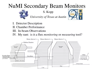
LINAC 4 and Beam Loss Parameters Bernd Dehning
Ionisation chamber SNS • Stainless steal • Coaxial design, 3 cylinder (outside for shielding) • Low pass filter at the HV input • Ar, N2 gas filling at 100 mbar over pressure • Outer inner electrode diameter 1.9 / 1.3 cm • Length 40 cm • Sensitive volume 0.1 l • Voltage 2k V • Ion collection time 72 us Bernd Dehning
Ionisation chamber LHC • Stainless steal cylinder • Parallel electrodes separated by 0.5 cm • Al electrodes • Low pass filter at the HV input • N2 gas filling at 100 mbar over pressure • Diameter 8.9 cm • Length 60 cm • Sensitive volume 1.5 l • Voltage 1.5 kV • Ion collection time 85 us Bernd Dehning
ACEM • Regular photomultiplier, with an aluminum foil as cathode (secondary electron emitter when irradiated). • 10 dynodes • High voltage: 0.5-1.5 kV • Max. current: 20 mA for short pulses • Electron transit time: 40 ns • Cathode surface area: 7 cm2 • Gain variation 1E3 U = 1000 V U = 600 V M. Palm AB-ATB-EA Bernd Dehning
Comparison of ACEM and Ionisation Chamber J. Bosser, G. Ferioli • ACEM 3 orders of magnitude more sensitive • ACEM disadvantage: gain depending on environmental B field Bernd Dehning
LHC acquisition board • Current to Frequency Converters (CFCs) • Analogue to Digital Converters (ADCs) • Tunnel FPGAs: Actel’s 54SX/A radiation tolerant. • Communication links:Gigabit Optical Links. • Surface FPGAs: Altera’s Stratix EP1S40 with 780 pin. • Current between 5 pA to 1mA • Minimum integration time 40 us Bernd Dehning
Summary • Beam loss and shower simulation are needed to make the choice for the detector and the locations • Definition of machine protection procedure needs to be done • Detector type: ionisation chamber or ACEM • LHC type electronics: main feature are appropriate • Definition of post mortem and logging, specifications are needed Bernd Dehning
Gain Variation of SPS Chambers • 30 years of operation • Measurements done with installed electronic • Relative accuracy • Ds/s < 0.01 (for ring BLMs) • Ds/s < 0.05 (for Extr., inj. BLMs) • Gain variation only observed in high radiation areas • Consequences for LHC: • Nogain variation expected in the straight section and ARC of LHC • Variation of gain in collimation possible for ionisation chambers Test with Cs137 • Total received dose: • ring 0.1 to 1 kGy/year • extr 0.1 to 10 MGy/year Bernd Dehning
SNS Bernd Dehning
Ionisation chamber currents (1 litre, LHC) Bernd Dehning