Download
1 / 44
440 likes | 561 Views
NuMI Secondary Beam Monitors. S. Kopp University of Texas at Austin I. Detector Description II. Chamber Performance III. In-beam Observations IV. My rant: is it a flux monitoring or measuring tool?. 3.0 2.5 2.0 1.5 1.0 0.5 0.0. 10 7 10 6. Alcove 1 Alcove 2 Alcove 3.

E N D
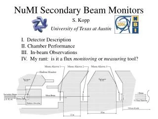
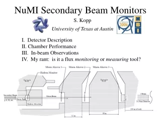
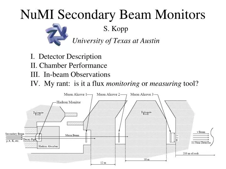
NuMI Secondary Beam Monitors S. Kopp University of Texas at Austin I. Detector Description II. Chamber Performance III. In-beam Observations IV. My rant: is it a flux monitoring or measuring tool?
3.0 2.5 2.0 1.5 1.0 0.5 0.0 107 106 Alcove 1 Alcove 2 Alcove 3 109 Particles / cm2 / spill Muons / cm2 / spill Radius (cm) Particle Fluences • Neutron fluences are ~ 10 that of charged particles at Hadron Monitor & Alcove 0 locations • Hadron Monitor insensitive to horn focusing • Muon Monitor distributions flat Robert Zwaska NBI 2003
Function of the Hadron Monitor • As alignment tool: • As target monitor Data! Monte Carlo (1st fin broken)
Function of the Muon Monitors HE Beam Alcove 2 Alcove 1 LE Beam Alcove 2 Alcove 1 Monte Carlo! Monte Carlo!
Requirements for Monitors • Concerns • High Rad Levels • Response to high particle fluences • Inaccessibility • Chambers inaccessible during beam operations • Hadron monitor activated to 58 R/hr after 1yr, impossible to repair (requires remote handling procedure to replace)
BPM x 334.2 BPM y 334.4 Detecting Phases of the Moon? Profile 334.9 Toroid 346.6 BPM x 346.9 BPM y • Initial efforts by the monitoring group focused too much on secondary beam monitors as a ‘single system’ which could diagnose every possible problem in NuMI beam • Better plan developed to many, smaller systems 347.4 Profile 356.1 Baffle 357.0 Target Hadron Monitor (alignment, target integrity) 357.7 Horn 1 Toroid (intensity) Baffle Thermocouple (halo) Horn Stripline (current) Muon Monitor (flux) SEM (spot size, position, halo) BPM (position) Crosshair 359.8 Horn BDot (B field) Target Budal (alignment) Crosshair 366.4 Muon Monitor Horn 2 Crosshair 369.4 Hadron Monitor 1077
Muon Monitor Arrays • 3 stations at 740,750,770m • 9x9 IC array • Max flux 4107m/cm2/spill • 3mm plate separation • Bias voltage 100V-500V
Am241 calib. source Annoyingly complex signal connection post Chambers Tray Kapton Cables
HV feedthrough Aluminum Wire Gasket HV connections Signal connections
Muon Monitor Calibration • 31 Tubes calibrated • Require 1% precision calibration • Tubes flushed with N2 gas • Each chamber irradiated with 1 Ci g-source. • Plateau currents for irradiated and non-irradiated configurations • Pressure & Temp monitored • Plateau current of single chamber for repeated source placements • Plateau currents for all 288 ion chambers • Plateau curve for one irradiated ion chamber
Hadron Monitor • Max flux ~109/cm2/spill • Rad levels ~2 x 10⁹ Rad/yr • 7x7 array of Ion Chambers • -1 mm gap • Residual activation 58R/hr • -Construction 54lbs Al, 4lbs stainless • Components Rad Tested up to 12GRad (6 NuMI years)
External cables Shield door Gas Lines Beam Absorber Kapton cable Support Rail
Radiation Testing (UT-Austin 1 MW fission Reactor) After After Ceramic Kapton Wire Before Peek • Exposed to 12GRad over 3 months. • Corresponds to 6 NuMI yr @ hadmon. After
Booster Beam Test Fermilab Booster Accelerator 8 GeV proton beam 5109 - 51012 protons/spill 5 cm2 beam spot size 10 November 2001 • Two chambers tested (1mm & 2mm gas gap) • 2 PCB segmented ion chambers for beam profile. • Toroid for beam intensity
High Intensity Beam Test • Key point: ion drift out of gas chamber can be slow compared to beam pulse - results in space charge • At highest intensity, chamber non-linear due to recombination in gas • Voltage plateau lost at high intensity
Compton e- (PuBe g’s) mMon Backgrounds from Neutrons PuBe Source Ryan Keisler Recoil Nuclei (from Neutrons) • Expect our chambers to see background neutrons mMon Alcove 1 with ~2108n/cm2/spill HadMon ~21010n/cm2/spill • These neutrons are few 10’s MeV can benchmark a toy MC of neutron scattering using a PuBe radioactive source (En ~ 1-10 MeV) • During normal NuMI beam operations: • Hadmon will see 0.3% background from neutrons • MuMon#1 will see 0.7% background from neutrons • During the December 3-4 test we hit the absorber directly with the proton beam • Expect signals from • Dump muons • neutrons PuBe Source GEANT MC of NuMI beam Ryan Keisler Debbie Harris Neutrons/cm2/2E13 POT Neutrons Energy (GeV)
Bench Tests • 3 chambers, Am241 source (Ea =5.3 MeV) • Setup useful to study • Chamber plateau • Electrostatic screening • Cross talk • Charge recombination Robert Zwaska NBI 2003
Thoughts on Early R&D • Too diffuse in questions asked -- Lacked decent MC • Too much focus on system that would survive Armagedden • Insufficient focus on systems issues • gas monitoring • calibrations • radiation field all around detectors, cables, etc • software systems • Required improved connection to rest of beam line • design for beam dump • layout of alcoves • infrastructure for chambers • Early FNAL-university difficulties
Gas Quality Annoyances Decrease flow Bad quality Gas added • Need laura’s plot showing gas issues.. Increase flow Increase flow again New gas bottles
Hadron Mon. Linearity 1.64 nC/1012ppp 1.46 nC/1012ppp Initial Operating Point Final Operating Point
Muon Chamber Linearity LE Beam Data • Linearity with particle fluence pretty good • Nonlinearity of 3% per 400pC seen – space charge?? slope16 pC/1012ppp
mMonitor Gas System Instrumentation HadMon Alc 1 Alc 2 Alc 3 • Needed even more redundant instruments available in case of failure • Since have added parallel instrumentation on gas quality (ion chambers outside in tunnel) • Monitor Temperature and Pressure to <1% to control detector signals Pressure (Torr) Termperature (°F)
Distribution & DAQ Racks Gas Delivery Line Gas System Installation Wiring Gas Rack High Pressure Manifold
Horn Current Stability Alcove 1 NuMI-only Mixed mode Alcove 2 Muon Horn Current (kA) Stripline Temperature (C)
Beam’s Eye View Graphite target Graphite protection ‘baffle’ Water cooling line Target Leak • Hadron Monitor signal on target dropped by 40% • we infer the equivalent of 41cm of water in the beam path Apertures Attenuation through water “Notch” indicates water level No Water No water Partially Full Target full Vertical Beam Position @ Target (mm) Horizontal Beam Position @ Target (mm)
Further Evidence of Multiple Scattering • Expect spot size at HadMon dominated by multiple scattering in target hall material: • If more material is present, we add radiation lengths: t/X0 (t/X0) + (t’/X’0) • Can use this distribution to derive extra radiation lengths. • Can see evidence of water, even horiz fin (pre-accident curves). • Decrease in s at gaps is helpful cross check, but difficult to use quantitatively since the beam is being clipped on the left and right, and is saturating the HadMon on the right. Horizontal Position @ Target (mm)
Target Recovery Water Pumped from Target Can • Target back-pressured and pumped • Progress tracked by hadron monitor • Water below level of the leak unable to be pumped, necessitated target removal and repair Partially Full No Water Multiple scattering through H2O Vertical Beam Position @ Target Water level indicated by beam instrumentation after efforts to drain target in place, confirmed with boroscope Cooling line
1st Attempt to Reinstall (Dried out) Target 4/20/05 • Notice the interesting feature – additional material in the beam? • Data at beam right starts to look a lot like pre-accident. • Flange was made incorrectly. Hadron Monitor RMS (mm) Hadmon Signal mV/1012ppp Hor. Beam Position @ Target (mm) Hor. Beam Position @ Target (mm)
Successful Reinstallation of Target • On 4/25, 4/27, and 4/28 scans were taken after fixing the problem of the spool piece interfering with the beam on the left side. • Shown below are the 4/28 data compared to the pre-leak data. • The scans actually look better because the spot size was larger in March. No Water No Water Hor. Beam Position @ Target (mm) Hor. Beam Position @ Target (mm)
horn baffle target Beam-Based Alignment of Target using mMon and HadMon • As beam scans horizontally or vertically, can strike • Target • Horn-protection baffle • Gap in between horn and target • Distance between struck-object and Horn 1 determines n energy Graphite protection ‘baffle’ Graphite target Water cooling line
Horizontal Target Scan (HE Position) • Target appears to be -1.5mm with respect to primary beam centerline.
baffle target selected target baffle
Closing Thoughts • We’d lacked a serious MC for the muon monitors, only solving this now after 1.5 years! • Monitor hardware performs well (2GRads!), and I’m thankful I don’t have any photos of it after irradiation in the beam (must look worse than Jim’s horn?!) • Hadron monitor has very useful online role, not so useful offline (rates difficult to predict) – acts as an alarm and diagnostic tool. • Muon monitors have tendency to be ignored online because we lack crisp interpretation for the data – some utility shown offline, however. • Fluxes are difficult to measure, but essential for cross section experiments. Key issues • muon monitors’ sensitivity/overlap with the n flux • backgrounds from d-rays, neutrons • Shielding geometry
References • S. Kopp et al, “The Secondary Beam Monitoring System for the NuMI Facility at FNAL,” accepted in Nucl. Instr. Meth. • R. Zwaska et al, “Beam-based Alignment of the Target Station Components of the NuMI Facility at FNAL,” accepted in Nucl. Instr. Meth. • D. Indurthy et al, “Study of Neutron-Induced Ionization for Helium and Argon Chamber Gases,” Nucl. Instr. Meth. A528, 731 (2003) • R. Zwaska et al, “Beam Tests of Ionization Chambers for the NuMI Beam at Fermilab,” IEEE Trans. Nucl. Sci. 50, 1129 (2003). • D. Naples et al, “Ionization Chambers for Monitoring in High-intensity Charged Particle Beams,” Nucl. Instr. Meth.A496, 293 (2003). • S. Kopp, “Accelerator Neutrino Beams,” submitted to Physics Reports, (available in SPIRES).