Download
1 / 26
260 likes | 267 Views
This study explores the impact of underlying topography on polarimetric backscatter in forests and crops using simulated data. The goal is to develop better forest scattering models for PolSAR imagery.

E N D
A SIMULATION STUDY OF TOPOGRAPHIC EFFECTS ON POLSAR CLASSIFICATION OF FORESTS AND CROPS M. L. Williams1 and T. L. Ainsworth2 1Cooperative Research Centre for Spatial Information 2Remote Sensing Division, Naval Research Laboratory IGARSS 2011, Vancouver
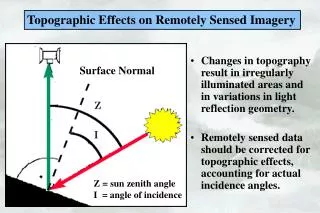
Methodology • Assess the Effects of Underlying Topography on Polarimetric Forest Backscatter Using Simulated Data • Estimate the Polarimetric Returns not Corrected by Orientation Angle Compensations • Compare orientation-angle corrected data against forest returns simulated over flat terrain • Simulated Imagery Allows One to Tease Apart Forest Scattering Mechanisms • Direct canopy backscatter, ground-trunk interaction, canopy attenuation, etc. • Goal: Use the Analysis of Simulated Data to Develop Better Forest Scattering Models for PolSAR Imagery IGARSS 2011, Vancouver
Forest Simulations Start With a Tree Model of a Scots Pine, ~18m in height Based on Detailed Measurements Upper Crown Primary and Secondary Branch Structures Lower Crown Dead Primary Branches Bare Vertical Trunk Detail of the Crown IGARSS 2011, Vancouver
To Make a Forest • Tree Branches Grow to Edge of Canopy Envelop • Upper Crown – Live Branches • Lower Crown – Dry Branches • Add Needles / Leaves • Generate a Set of Unique Trees • Semi-Randomly Plant the Forest: IGARSS 2011, Vancouver
Scene Generation View from Radar Platform at Mid-track • A realization of a random, sloped ground surface generated according to surface roughness, soil moisture and slope parameters. • Ground surface covered by layer of random vegetation. • A forest stand realized as a circular area populated by trees. • Trees have a distribution of heights around the supplied mean value. • Tree positions are determined by shuffling from an initially uniform grid, with a crown-overlap cost function. • Red envelopes mark “living” pine crown, grey layer is “dry” timber. • Each tree is unique and realized in detail for SAR simulation. IGARSS 2011, Vancouver
SAR Simulator – PolSARproSim • Basic Simulations Performed with Stand-alone Version of the PolSARproSIM Software • Coherent, polarimetric SAR simulator • Methodology documented within PolSARpro • Five Basic Scattering Components • Signal attenuated by all vegetation layers Ground-Forest Backscatter Ground / Short- Vegetation Return Direct Forest Direct Short Vegetation Direct Ground IGARSS 2011, Vancouver
Scene Summary • Primary Characteristics • Scots Pine forest - ~2600 trees • Relatively sparse canopy with large trunk structure • Mean tree height: 18m • Mean canopy radius: 2.6m • Canopy attenuates radar signals • Low vegetation ground cover • Weak scatterer, weak signal attenuation • Moderately rough, moist ground surface • Range and/or Azimuth Ground Slopes • Independent variables in this initial study • Coupled Radar Scattering Components • Attenuation, Ground Slopes & Multiple Scattering IGARSS 2011, Vancouver
Polarimetric Analysis • A Select Set of Polarimetric Descriptors: • Orientation Angle: • Related to range() and azimuth() slopes • The complex phase of the RR-LL correlation (circular basis) • -angle: Average scattering mechanism • Surface: 0°, Dipole: 45°, Dihedral: 90° • Double Bounce Scattering Strength • Dominant scattering mechanism in our (current) simulated forest • Arises primarily from ground-trunk interactions • Circular Basis Correlations • |4|: Reciprocal of orientation angle variance • Magnitude of the RR-LL correlation • Independent of the underlying scattering mechanism • |r|: Reciprocal of the shape variation • Relates to the variance of the effective scatterer shape • Depends explicitly on the scattering mechanism IGARSS 2011, Vancouver
A SAR Image RealizationL-band, 5 Meter Resolution RGB Image:HH,HV, VV • Forest covered central region • Low vegetation area surrounds forest • Range increases from left to right HH HV VH VV IGARSS 2011, Vancouver
-angle Histograms Range Slope: 0°, 1°,2° & 4° Rapid decrease of high components between 0° & 2° Azimuth Slope: 0°, 6°,8° & 10° No change until ~6° slope then a shift to lower values IGARSS 2011, Vancouver
Range Slopes in Grassy Regions Orientation Angle & Correlation |4| With azimuth slope set to zero, the orientation angle does not depend on range slope. Low orientation angle correlations without a strong dependence on range slope. Slightly lower for positive slopes. IGARSS 2011, Vancouver
Range Slopes in Forest Area Double Bounce Power & Ground-Forest Component Grass Region Forest Small range tilt reduces double bounce power in forest, but not in the grassy regions. Ground-Forest Component The ground-forest multiple scattering accounts for the rapid drop of the double bounce backscatter. All tree trunks are perfectly vertical – not a good approximation. IGARSS 2011, Vancouver
Azimuth Slopes in Grassy Regions Orientation Angle & Correlation |4| The orientation angle basically matches changes in azimuth slopes. Low correlation values imply poor estimates of orientation angles. IGARSS 2011, Vancouver
Azimuth Slopes in Forest Area Double Bounce Power Grass Region Forest Small azimuth tilts allow ground-trunk scattering, only larger slopes reduce double bounce power in forest. Ground-Forest Component The ground-forest multiple scattering component accounts for double bounce changes with azimuth slope. Tree trunk forward scattering is not limited to specular directions. IGARSS 2011, Vancouver
Azimuth Slopes in Forest Area Orientation Angle & Correlation |4| The orientation angle basically matches changes in azimuth slopes. Higher correlation values in forest area imply good estimates of the orientation angles. IGARSS 2011, Vancouver
Azimuth Slopes in Forest Area Orientation Angle Full SAR Simulation Orientation angle estimates from full SAR simulation closely matches the orientation angles of the strong ground-forest scattering component. The ground-forest induced orientation angle shows low variance (high correlations) independent of azimuth slope. The orientation angle variance from the full simulation increases with increases in the azimuth slope. Ground-Forest Component IGARSS 2011, Vancouver
Azimuth Slopes in Forest Area Scatter Shape Variation Full SAR Simulation The Shape Variation reflects inherent changes to the polarimetric scattering. Even after orientation angle compensation, once the azimuth slopes exceed ~6°, the ground-forest scattering component changes character. The double bounce scattering, probably generated from ground-trunk interactions, is greatly reduced. This change in Shape Variation is consistent with the -angle changes due to azimuth slopes shown earlier. Ground-Forest Component IGARSS 2011, Vancouver
Major Forest Scattering Components Forest scattering, at least for our simulated Scots Pine forest, is almost completely specified by the Direct Forest (blue) and the Ground-Forest (green) scattering components. The cyan curve, the combination of Direct Forest and Ground-Forest scattering, almost exactly matches the Full Scattering curve (red). Grassy Region Forest Returns IGARSS 2011, Vancouver
Major Forest Scattering Components The Full Orientation Angle Correlation matches the Correlation formed from the Direct Forest and Ground-Forest scattering components. Similarly, the Full Shape Variation reflects the combination of the Direct Forest and Ground-Forest scattering. IGARSS 2011, Vancouver
Preliminary Conclusions (1) • Results Based on a Single Forest Simulation • Relatively light canopy attenuation • Sparse forest – typical of Scots Pine • Known Defects in the Tree Realizations • All tree trunks aligned perfectly vertical • One can design trees with randomly angled trunks • Only Investigated Polarimetric Variations with Ground Slope • Wider variety of forest parameters needed • Adjust relative weighting of canopy attenuation, direct ground scattering, tree architecture, etc. • Simulations May Produce Artificial Artifacts Not Seen in Scenery • Blind use or application of software may be misleading IGARSS 2011, Vancouver
Preliminary Conclusions (2) • Both Range and Azimuth Slopes Reduce Double Bounce Ground-Trunk Scattering in this Forest • Both orientation angle correlation and shape variation indicate inherent changes in polarimetric scattering due to topographic slopes • Orientation Angle Compensation Does Not Remove All Topographic Effects on SAR Polarimetry • The Large Number of Forest Parameters May Limit Full Investigation • Tree architecture, relative ground / canopy scattering strength, and canopy attenuation may be the important variables IGARSS 2011, Vancouver
Background IGARSS 2011, Vancouver
Z N Y O X Volume of Spheroid Scatterers • Assuming a cloud of spheroids for volumetric canopy scatterers, characterized by independent parameters: size, shape and orientation. Each elementary scatterer features a body of revolution w.r.t. the symmetric axis, ON. The projected symmetry axis on the polarization plane is oriented towards angle b; The local incidence angle w.r.t. the symmetry axis is y; The principal scattering components are Sa and Sb. IGARSS 2011, Vancouver
Circular Polarization Representation • Oriented targets can be clearly expressed in the circular polarization basis • Mean orientation angle from the phase of RR-LL • Similar to circularly polarized weather radar analysis If b and y are separable, Symmetric distribution Orientation dispersion Mean orientation angle Independent of orientation 0: sphere 1: dipole Advantage: Orientation parameters readily separable as phase terms. Relates to both shape variation and orientation dispersion IGARSS 2011, Vancouver
Orientation Distribution • The orientation angle is close to a von Mises distribution Established a relation between r2 and r4. The orientation parameters, mean and dispersion, can be determined and removed, which leaves only scatterer shape information. IGARSS 2011, Vancouver
Orientation Shape Size Physical Parameters Retrieval • It is then straightforward to solve the principal components from orientation compensated data • Theoretically, the solution works for a single volume scattering mechanism and homogenous targets, resolving parameters: We get mean shape and shape variation. IGARSS 2011, Vancouver