Download
1 / 28
280 likes | 437 Views
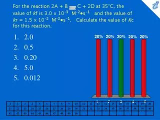
Fully integrated 533 MHz programmable switched current PLL in 0.012. Wilson, P.R.; Wilcock, R.; Al Hashimi, B.M.; Electronics Letters Volume 44, Issue 22 , October 23 2008 Page(s):1297 - 1298 Digital Object Identifier 10.1049/el:20082451 學 生: 莊明龍 學 號: m97662001

E N D
Fully integrated 533 MHz programmable switched current PLL in 0.012 Wilson, P.R.; Wilcock, R.; Al Hashimi, B.M.;Electronics LettersVolume 44,Issue 22, October 23 2008 Page(s):1297 - 1298 Digital Object Identifier 10.1049/el:20082451 學 生: 莊明龍 學 號: m97662001 日 期: 98年05月11日 彰化師範大學積體電路設計研究所
Outline • Abstract • Introduction • Switch current PLL design • Experimental results • Conclusions
Abstruct • A 533 MHz programmable phase-locked loop is designed for DDR applications using a switched current filter and implicit phase detection. • The circuit occupies only 0.012 mm2 on a 0.12 mm 1.2 V digital CMOS process.
INTRODUCTION • Switched currents (SI) is a current mode sampled analogue data technique that requires no passive components and is therefore compatible with a standard digital CMOS technology. • Implicit phase detection(IPD) is an elegant technique which uses the inherent sampling nature of a sampled loop filter to achieve phase detection.
INTRODUCTION • Not only does this circumvent problems that are associated with using a sampled data loop filter but it also removes the need for a separate phase detector block, thus saving area and complexity.
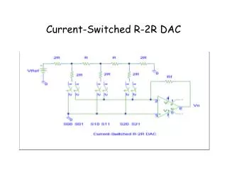
Switch current PLL design • Switched current PLL architecture
Switch current PLL design • Through careful design of the filter’s sample and hold circuit, phase detection can be achieved implicitly. • This implicit phase detector operation can be approximated to a two-part model which consists of a phase error function followed by a single pole system:
Switch current PLL design • If following guidelines are met, the IPD characteristics can be approximated to a constant gain of 0.66 A. • The IPD pole is at least ten times greater than the loop natural frequency . • The SI memory cells in the sample and hold stage of the loop filter are designed for a time constant of nine times that of the time constant of the SI cells in the rest of the filter.
Switch current PLL design • SI loop filter signal graph
Switch current PLL design • Implementation
Switch current PLL design • At the circuit level, a double sampled class AB SI bilinear integrator is used owing to its ability to improve memory cell output conductance and operate at low voltage levels . • Matched class AB current mirrors are used to implement the scaling blocks and the sample and hold circuit is implemented with a double sampled class AB SI memory cell.
Switch current PLL design • ICO architecture
Switch current PLL design • Delay cell structure
Experimental results • Chip micrograph of SI PLL • standard 120 nm CMOS digital technology • 1.2 V digital supply voltages • 1 V analogue supply voltages.
Experimental results • The complete size of the programmable PLL core is 100*120 mm giving an area of 0.012 mm2. • For testing purposes a selectable divide by four output stage was integrated to overcome pad cell bandwidth limitations.
Experimental results • Programmable modes of operation
Experimental results • Measured PLL output jitter
Experimental results • Measured performance summary
Conclusions • One drawback of fully integrated PLLs is the area overhead due to integrated loop filter capacitors. This Letter demonstrates that the SI PLL technique gives excellent potential for extremely compact and fully integrated layouts. • This has been illustrated through the fabrication of a 533 MHz programmable PLL for DDR applications which occupies just 0.012 mm2 and consumed just 3.6 mW.
Conclusions • SI PLLs should be considered as a viable alternative wherever compact implementations of fully integrated PLLs are required.
appendix. Implicit phase detector • Sample and hold waveforms
appendix. Implicit phase detector • PD Transfer characteristic of ideal sample/hold
appendix. Implicit phase detector • Waveforms for the SI phase detector
appendix. Implicit phase detector • PD Transfer characteristic of SI memory cell