Download
1 / 46
460 likes | 465 Views
Low IF topologies for fully integrated receivers. Presented by Hamed Narimani Spring 2007. Outline. Introduction IF Receivers Zero-IF Receivers Complex signals Analog Integrated Complex Filters Receiver with complex signal structure Quantization error bound in CORDIC algorithm.

E N D
Low IF topologies for fully integrated receivers Presented by Hamed Narimani Spring 2007
Outline • Introduction • IF Receivers • Zero-IF Receivers • Complex signals • Analog Integrated Complex Filters • Receiver with complex signal structure • Quantization error bound in CORDIC algorithm
Introduction • Two main types of receivers (whether or not an IF is used): • Heterodyne : IF receiver • Low integration level • Image problem expensive • Homodyne : Zero-IF receiver • very high integration level • DC offset problem low cost but poor performance due to IF receiver
Introduction • Fundamental Trade-off in Receiver • Using one or more IF stages to relax the filter requirements, but need to deal with images • Using image reject mixers with I&Q LO signals to eliminate the need of band-pass filters (to enable higher level of integration) • RF ICs typically employ a combination of simple mixing with some image filtering and image reject mixing
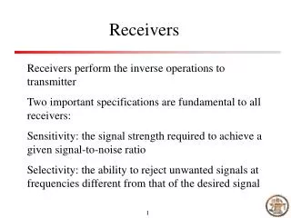
IF Receivers • The wanted signal is downconverted from its carrier to the IF by multiplying it with a single sinusoidal signal
IF Receivers • The main disadvantage is mirror signal: when the wanted signal is suited on fc ,the mirror frequency is at fc-2fi
IF Receivers • The mirror freq. has to be suppressed before it is mixed down to the IF • This is done by means of a HF filter • Such an HF filter can only be realized if fi is high enough( wanted signal will be relatively far away from mirror frequency • Even when the ratio fc/fi is about 10, the specifications for HF filter is very severe: • Very high Q (up to 50 and more) • High order (up to sixth order for high-quality application ,i.e., 60-70 –dB mirror freq. suppression) • In some cases, the center freq. must be tunable • Discrete HF filter : expensive and vulnerable • The IF signal ,has to be filtered to extract the wanted signal. • This is done by means of an IF filter. This filter too must have: • High Q (e.g., 50) • High order (eighth or tenth order) • Discrete IF filter (e.g., ceramic resonators) • The performance (achievable dynamic range over power consumption) of integrated active bandpass filters is intrinsically Q-times worse than passive filters. discrete passive bandpass filters will be a lot better than an active integrated version if one is concerned with power and area. • Discrete components are very expensive
IF Receivers • Often the IF is too high for the A/D converter, and then one or more extra IF stages are used. The final IF is often situated around 1 MHz.
Zero-IF Receivers • The wanted signal is directly downconverted to the baseband.(the IF is chosen to be zero)
Zero-IF Receivers • The signal on the mirror frequency is the wanted signal itself. they are each others mirror image. • This results in the lower and upper sideband being placed on top of each other in the baseband. • This problem is solved by doing the downconversion twice: once with a sine and once with a cosine.
Zero-IF Receivers • The original signal m(t) can, in case of phase modulation, be found as the angle of vector[vi(t),vq(t)], a lowpass filtered version of [ui(t),uq(t)]: • The demodulation in DSP can be done by means of an angle measurement algorithm ,e.g., CORDIC algorithm. • Advantages of zero-IF receivers: • The main advantage of zero-IF receivers is: there is no need for a high Q tunable bandpass filter. The lowpass filters can easily be realized as analog integrated filters • In an IF receiver, extra suppression is needed because the signal on the mirror freq. can be bigger than the wanted signal:
Zero-IF Receivers • Main disadvantages of Zero-IF receivers: • DC offset • I&Q phase and gain mismatch • DC offset is mainly a result of the crosstalk between the RF and LO inputs and is superimposed on the wanted signal in the baseband • DC offset can saturate ADC and lowpass filter and produce even order distortion in LNA • It can only be removed by means of very long time constants (at least one-tenth of a second) • DC offset is the main problem that has kept the zero-IF receiver from use in practical applications • It is only with the introduction of DSP’s that this problem has become controllable (based on digital signals)
Zero-IF Receivers • In DSP a complex nonlinear scheme can be used to determine the DC-level dynamically. This value can then be fed back to analog part
Zero-IF Receivers • Is it possible to realize a receiver which combines the advantages of both known receiver types? • If one would use two downconversion path in an IF receiver, all required information for the separation of the wanted signal from the mirror signal would still be available in the two IF signals. • The high IF, can now be replaced by a low IF (e.g., one or two times the bandwidth of the wanted signal) • A high quality HF filter would not be necessary anymore • The IF filters becomes now a set of two low Q(Q=1 or 2) bandpass filters whose integration is as easy as the integration of the lowpass filters for a zero-IF receiver • How such a receiver can be realized? • In the next section the complex signal technique is introduced • This technique will be used to analyze the Zero-IF topology • The limitation of systems which use complex signals will be analyzed • The low-IF receiver topology will be synthesized from Zero-IF topology
Complex signals • A polyphase signal is a vector of independent signals • Two-phase signals are called complex signals and the complex notation is used for them: • Every frequency component of u(t) can be written as a sum of two sequences. The two sequences of a real signal always have the same amplitude and the opposite phase. • The first sequence has only a positive frequency component and the second only a negative
Complex signals • Sum of two complex signals: • Multiplication:
Complex signals • Only the signal suited on negative freq. is downconverted and there is no superposition of the lower and upper sideband at the baseband
Complex signals • Complex filtering • Realization of a complex filter: • Realization with real filters very costly. for instance a first-order filter with a complex pole, requires the use of four real second-order filters • Direct synthesis: realization with complex summators, amplifiers and integrator
Complex signals • Imperfections in complex systems: complex operators are made with pairs of real operators. So the performance of the system degrades when they are not perfectly matched. • In digital systems, matching can be perfect; but in analog is unavoidable • The result of mismatch is phase error and amplitude error and consequently a mirroring of signals to their opposite frequency • e.g., phase error: • The ratio between the unwanted and wanted signal is a phase error of 1degree results in -35-dB crosstalk between positive and negative frequencies
Complex signals • Constant amplitude error
Complex signals • Phase error: • Ferq. Dependent amplitude:
Complex signals • The mirror error component that is caused by amplification can be corrected with the use of two matched AGC’s in the real and imaginary signal path. • Amplitude error is then determined by the matching between AGC’s. In a DSP, AGC’s can be implemented accurately. • But this is only possible for circuits in which there is no physical coupling between two paths only in circuit topologies in which only real operations are performed on complex signals • Practically, phase and amplitude error can only be corrected when they are frequency independent or at least constant in the passband
Complex signals • Quadrature oscillators often use an RC-CR circuit to obtain 90 degree phase shift. RC mismatch or parasitic effects result in a phase error
Analog Integrated Complex Filters • A complex bandpass filter can be found by frequency translating a lowpass filter: • E.g., the translation of a single pole is:
Receiver with complex signal structure • The wanted and the mirror signal are downconverted to the IF • The wanted signal is suited at negative freq. and the mirror signal is suited at positive freq. • The IF can be low (a few hundred kilohertz i.e., one or two the signal bandwidth), because there is no need for any HF mirror signal suppression • Further downconversion of IF signal can be down in two ways:
Receiver with complex signal structure • Mirror signal is first suppressed with a complex bandpass filter ,i.e., shifted lowpass filter, centered around the IF freq. • The final downconversion to the baseband can be done with multiplication with a sine • The required dynamic range of the A/D-converter (number of bits) is the same as for a zero-IF receiver • Digital applications require about 6-8 bits, high quality continuous-time applications will requre 10 bits
Receiver with complex signal structure • A real bandpass filter is used to separate both the wanted and the mirror signal from their neighbors • The final downconversion to the baseband must be done with a positive freq. equal to IF • In this topology, not only the wanted signal, but the wanted signal together with the mirror signal, is sampled. The mirror signal can be 20-30-dB higher than the wanted signal. Therefore, 4-5 extra bits are requred • Low cost digital applications will be satisfied with 12 bits
Receiver with complex signal structure • Comparing Zero-IF and Low-IF receivers: • There is absolutely no DC problem in Low-IF receivers, because the wanted signal is not suited around DC • In low-IF receivers the suppression of mirror signal must be higher, because the mirror signal is not the same as the wanted signal and can be higher than it: • In Zero-IF, a 40-dB suppression results in an SNR of 40-dB for the wanted signal • In Low-IF, a suppression of 70-dB is required for an SNR of 40-dB when the mirror signal can be 30-dB higher than the wanted signal • The required suppression is determined by the negative to positive freq. crosstalk of the complex building blocks, and this is determined by matching • The most important matching problem is the phase error which is induced by quadrature oscillator.
Quantization error bound in CORDIC algorithm • In order to dimension the CORDIC-DDC it is necessary to estimate the achievable accuracy. • The maximum overall quantization error of a fixed point CORDIC processor after n iteration, can be calculated as: • : the ideal output vector (theoretically produced by a CORDIC processor with infinite precision arithmetic after an infinite number of iterations) • : the output vector computed by the finite precision CORDIC
Quantization error bound in CORDIC algorithm • : angle approximation error • : rounding error vector With: : maximum absolute input quantization error bound in x0 and y0 :maximum absolute rounding error in xi and yi due to bit truncation with fixed point arithmetic (b fractional binary digits)
Quantization error bound in CORDIC algorithm • : resulting error component in vn due to the rounding errors in zi that are caused by the input quantization of z0 and the quantized fixed point representation of the basic rotation angles and arctan(2-i), respectively:
Quantization error bound in CORDIC algorithm • Beside the overall quantization error power, its spectral distribution is an important property, i.e., the spectral purity. • A worst case assumption would be to concentrate the error in one discrete spur. • This would give a bound for the spurious free dynamic range (SFDR) i.e., the ratio of the power of the desired signal, and the power of the strongest spur. • Downconverting a 20 MHz tone to DC with 16 iteration, 18 fractional binary digits and ideal ADC approximately 98-dB SFDR • Downconverting a 20 MHz tone to DC with 16 iteration, 18 fractional binary digits and 12 bit ADC approximately 70-dB SFDR
Quantization error bound in CORDIC algorithm • For typical signals and ADCs the SFDR is mainly determined by the quantization of the input signal rather than the quantization effects within the CORDIC-DDC • Quantized harmonic signals produce an error spectrum which is much worse conditioned than that of typical signals e.g., in communication applications
Thank you for your consideration