Download

1 / 60
600 likes | 737 Views
Cross Country Flight Planning. PTS Requirements. Exhibits adequate knowledge of the elements by presenting and explaining a preplanned cross-country flight . It should be planned using actual weather reports/forecasts and conform to the regulatory requirements

E N D
PTS Requirements • Exhibits adequate knowledge of the elements by presenting and explaining a preplanned cross-country flight. It should be planned using actual weather reports/forecasts and conform to the regulatory requirements • Exhibits adequate knowledge of the aircraft’s performance capabilities by calculating the estimated time en route and total fuel requirement based upon factors, such as— • Power settings • Operating altitude or flight level • Wind • Fuel reserve requirements • Weight and balance limitations
PTS Requirements • Selects and correctly interprets the current and applicable en route charts, instrument departure procedures (DPs), RNAV, STAR, and Standard Instrument Approach Procedure Charts (IAP) • Obtains and correctly interprets applicable NOTAM information • Determines the calculated performance is within the aircraft’s capability and operating limitations • Completes and is able to file a flight plan in a manner that accurately reflects the conditions of the proposed flight • Demonstrates adequate knowledge of GPS and RAIM capability, when aircraft is so equipped • Icing • Demonstrates the ability to recognize wing contamination due to airframe icing • Demonstrates adequate knowledge of the adverse effects of airframe icing during pre-takeoff, takeoff, cruise, and landing phases of flight and corrective actions • Demonstrates familiarity with any icing procedures and/or information published by the aircraft manufacturer
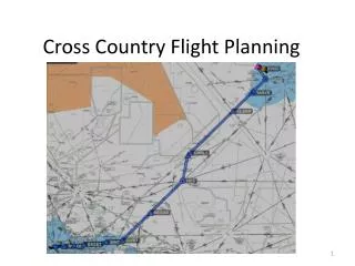
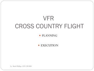
Cross-Country Flight Planning • Let’s plan a flight from KVGT to KLAX • The first thing I do is look at the magic magenta line for a direct flight on a VFR sectional chart to get an overview based on the IFR planning elements Restricted area Fort Irwin – GPS jamming potential Terrain too high for aircraft climb performance MOA
Preflight Planning Elements §91.103 • Each pilot in command shall, before beginning a flight, become familiar with all available information concerning that flight. This information must include— • For a flight under IFR • Weather reports and forecasts • Fuel requirements • Alternatives available if the planned flight cannot be completed • Any known traffic delays of which the pilot in command has been advised by ATC • Determine whether traffic delays might require holding
Preflight Planning Elements §91.103 • Each pilot in command shall, before beginning a flight, become familiar with all available information concerning that flight. This information must include— • Runway lengths at airports of intended use • Runway length should be at least 150% of values shown in the POH/AFM, or at least 200% of the POH/AFM numbers for a wet, icy, or otherwise contaminated runway • Consider whether LAHSO procedures are in use • Takeoff and landing distance information from the POH under expected values of airport elevation and runway slope, aircraft gross weight, and wind and temperature
The Route • Departure airport considerations • Departure procedures • Enroute considerations • Arrival considerations • Approach considerations • Destination airport considerations
Departure Airport Considerations • Frequencies • Clearance delivery process • Taxi • Hot spots • Route • Weather • Ceiling – can I get back to land? • Visibility • Winds vs runways and obstacles (obstacle clearance is based on groundspeed!) • Runway choice • Does it impact the departure procedure • Length • Delays
Departure / Destination Airport Considerations Frequencies (be sure to listen to ATIS for weather and airport information) • Airport diagram and Airport facility directory are good places to start Taxiways Hot spots Determine your location to understand your taxi route Runway data
Departure Runway Planning • Can we take off given the aircraft weight, pressure altitude and temperature? • Runway required • Airport elevation 2205’ • Metar = VGT 300553Z 32014KT 10SM OVC095 13/02 A2993 RMK AO2 SLP149 • 29.93 =-10’ = 2195’ PA • Ground roll = Plenty of runway as shortest runway is 4203’ per AF/D
Runway Planning • Also consider runway slope impact, even if no factor is included in the take-off distance chart • Rule of thumb • Downslope takeoff distance is reduced about 5% per degree • Upslope takeoff distance is increased about 7% per degree • Listed in airport’s runway information in AFD, on taxi diagrams and on approach plate runway diagrams • If the runway distance is close to operational limits of the aircraft, be sure to compute the 50’ obstacle clearance distance to be sure take-off is viable
Runway Planning • Be sure to check Notams • Runway closures / limits • Taxiway closures / limits • Lighting outages • Examples
Clearance Delivery • Towered airport • Ground control / tower • Clearance delivery • May be able to receive a pre-taxi clearance - can get clearance up to 10 minutes prior to beginning taxi • Non-towered airport • FSS by Phone • FSS by Radio • May have remote communications outlet (RCO) • Ground Communication Outlet (GCO) - VHF radio to telephone connection to FSS – usually four key clicks on the radio to contact ATC and six key clicks to contact the FSS • ATC by radio • Depart the airport VFR if conditions permit and contact ATC for your clearance in the air • Void time - Must depart before the clearance void time; if you fail to depart, you must contact ATC by a specified notification time, which is within 30 minutes of the original void time
Obtaining the Clearance INITIAL RADIO CONTACT • In your initial radio communication with the clearance facility state: • Aircraft identification • Location on the airport • Type of operation planned (ifr) • Point of first intended landing and requested action (taxi/clearance on request/etc)
IFR Clearance Items • Clearance will be issued prior to take-off and will include the following items as appropriate, in the order listed: • Aircraft identification • Clearance limit • Departure procedure or SID • Route of flight • Altitude data in the order flown • Holding instructions • Any special information • Frequency and beacon information • Readback clearance items
Weight and Balance Planning • Compute a weight and balance for the take-off weight through the landing weight to be sure you are within CG for the entire flight and not overweight at take off or landing • Can do with a computer program or by hand from the aircraft’s weight and balance Take off Landing zero fuel
Airport EnvironmentAvoiding Runway Incursion • Stop bars - Row of red unidirectional, in-pavement lights installed along the holding position marking. When extinguished by the controller, they confirm clearance for the pilot or vehicle operator to enter the runway • Taxiway centerline lights - Work in conjunction with stop bars, are green in-pavement lights that guide ground traffic under low visibility conditions and during darkness • Runway guard lights - Elevated or in-pavement alternately flashing yellow lights, used to denote both the presence of an active runway and identify the location of a runway holding position marking
Airport EnvironmentAvoiding Runway Incursion • Clearance bars - Three yellow in-pavement lights that mark holding positions for aircraft. When used for hold points, they are co-located with geographic position markings • Geographic position markings - Used as hold points or for position reporting. They are “pink spots” outlined with a black and white circle and designated with a number, a letter, or both • Runway entrance lights - String of lights in center of taxiways/runway crossings illuminated red when there is high-speed traffic on or approaching the runway
Instrument Departure Procedures (DPs) • Departure procedures (DPs) are preplanned routes that provide a way to depart the airport and transition safely to the en route structure • Two types • Obstacle Departure Procedures (ODPs) which are printed either textually or graphically • Standard Instrument Departures (SIDs) which are always printed graphically • Higher than standard climb gradients are specified by a note on the departure procedure chart for graphic DPs, or in the Take-Off Minimums and (Obstacle) Departure Procedures section of the TERPS • AIM 5-2-8(e) provides that a pilot, prior to departing an airport on an IFR flight should: • Consider the type of terrain and other obstacles on or in the vicinity of the departure airport; • Determine whether an ODP is available; • Determine if obstacle avoidance can be maintained visually or if the ODP should be flown; and • Consider the effect of degraded climb performance and the actions to take in the event of an engine loss during the departure. Pilots should notify ATC as soon as possible of reduced climb capability in that circumstance
Obstacle Departure Procedure • ODPs are printed either textually or graphically • Graphic ODPs will have (OBSTACLE) printed in the procedure title • ODPs provide obstruction clearance via the least onerous route from the terminal area to the appropriate en route structure • ODPs are only used for obstruction clearance • An ODP may drastically affect the initial part of the flight plan. You may have to depart at a higher than normal climb rate, or depart in a direction opposite the intended heading and maintain that for a period of time, any of which would require an alteration in the flight plan and fuel planning
Obstacle Departure Procedure • ODPs may be flown without ATC clearance, unless an alternate departure procedure (SID or radar vector) has been specifically assigned by ATC • As a general rule, ATC will only assign an ODP from a non-towered airport when necessary for aircraft to aircraft separation • ATC, however, assumes that you will use a published ODP when departing from a non-towered airport • ATC must be notified if you do not have ODPs available by noting "no DP" in the flight plan or by advising ATC • Can enter “will depart (airport) (runway) via textual ODP in remarks section of flight plan • A graphic ODP may also be filed in an instrument flight plan by using the computer code included in the procedure title • ODP procedures are listed in the front of the approach chart booklets under the heading Takeoff Minimums and Obstacle Departure Procedures. Each procedure is listed in alphabetical order by city and state • Graphical procedures are included with the airport information in the TERPS
Obstacle Departure Procedure • When should you fly an ODP? • In most cases, but especially at night, in IMC and in marginal VMC • When departing without an ODP or SID, how can you ensure terrain/obstacle clearance until reaching a published MEA? • Obstacle clearance for all departures, including diverse, is based on the pilot crossing the departure end of the runway at least 35 feet above the departure end of runway elevation, climbing to 400 feet above the departure end of runway elevation before making the initial turn, and maintaining a minimum climb gradient of 200 feet per nautical mile (FPNM), unless required to level off by a crossing restriction, until the minimum IFR altitude • Back cover of Terps has a climb rate table • 90 knots = 300 ft/min for 200’ NM • 120 knots = 400 ft/minfor 200’ NM • Computed as: Ground speed / 60= NM/min NM/min X required climb gradient = Required feet per min rate
Obstacle Departure ProcedureGraphical Climb rates required • Graphical procedure shows the route graphically and includes a textual description as well Obstacle notes Route description
Obstacle Departure ProcedureTextual • Textual ODPs are described in the front of the TERPS booklet in the Takeoff Minimums section Textual ODP Cross reference to KVGT’s graphical ODP
Obstacle Departure ProcedureIndication • To determine if an airport has alternate take off minimums or an ODP look for a triangle T in the approach plates or in the Take-Off Minimums and (Obstacle) Departure Procedures section of the TERPS
Standard Instrument Departure Procedure • SIDs are air traffic control (ATC) procedures printed in graphic form to provide obstruction clearance and a transition from the terminal area to the appropriate en-route structure • SIDs are primarily designed for system enhancement and to reduce pilot/controller workload, but consider obstacle clearance • Unlike an ODP, ATC clearance must be received prior to flying a SID • If you do not have SIDs or do not want to fly them place the statement “NO SIDs” in the remarks section of your flight plan • You are not required to depart using a SID
Standard Instrument Departure Procedure Climb rates • SIDs are included in the TERPS immediately after the applicable airport’s approach plates • SID charts depict the departure route, navigational fixes, transition routes, and required altitudes • Review vector SID charts prior to use because they often include nonstandard lost communication procedures Limits / notes Obstacle notes Route description
Standard Instrument Departure Procedure • Typically, transition routes fan out in various directions from the end of the basic SID to allow pilots to choose the transition route that takes them in the correct direction • A transition route includes a course, a minimum altitude, and distances between fixes on the route • To file a SID in your route include the code from the bottom of the plate – eg. NOTWN3.LAS in the route described in the flight plan • When filing a SID for a specific transition route, include the transition in the flight plan, using the correct departure and transition code • clearance from ATC will include both the departure name and transition e.g., Joe Pool Nine Departure, College Station Transition
Departure Procedure Nomenclature • Based upon equipment required • Non-RNAV DP - Established for aircraft equipped with conventional avionics using ground-based NAVAIDs • RNAV DP - Established for aircraft equipped with RNAV avionics; e.g., GPS, VOR/DME, DME/DME, RNP, etc. • Radar DP - Radar may be used for navigation guidance for SID design. Radar SIDs are established when ATC has a need to vector aircraft on departure to a particular ATS Route, NAVAID, or Fix • Based on Nav Responsibility • PILOT NAV – • Allows you to provide your own navigation with minimal radio communication • May include initial radar vectors to help you join the procedure, but the majority of the navigation will remain the pilot’s responsibility • VECTOR SIDS • Usually requires ATC to provide radar vectors from just after takeoff until reaching the assigned route or a fix depicted on the SID chart • Procedure does not include departure routes or transition routes because independent pilot navigation is not involved
Departure Procedure Vector Sid Example Pilot Nav Sid
Takeoff Minimums • FAA establishes takeoff minimums for every airport that has published standard instrument approaches • Used by commercially operated aircraft - Part 121 and 135 - 1 statute mile visibility for single and twin engine aircraft • Smart to use for Part 91 operations, but not required • NACO charts list takeoff minimums only for runways with non-standard minimums • Listed by airport in alphabetical order in the front of the TERPS • Airport with non-standard takeoff minimums, has a “triangle T” or “trouble T” in the notes section of the instrument procedure chart
Departure Procedures are Important • On November 8, 2007, a Cessna T182T, on a route similar to our direct magenta line, was destroyed after impacting Potosi Mountain during climb to cruise, about 13 miles southwest of Las Vegas after departing KVGTon a SW heading. Both ATP rated pilots were killed. Had they followed the departure procedure, the mountain could have been avoided. On January 16, 1942, 15 minutes after takeoff from Las Vegas Airport (now Nellis Air Force Base) the TWA aircraft slammed into Potosi Mountain, at an elevation of 7,770 ft, and was destroyed
What’s Our Departure Plan • Consider the departure paths in the SIDs and determine if you can use a DP • ODP - Possible • Rightturn – doesn’t serve runways 30L/R – so not good for us • Northtown - Possible • Be sure to check notes on the procedure – can you meet the requirements • Can you meet the climb gradient to specified altitude • Metar = VGT 300553Z 32014KT 10SM OVC095 13/02 A2993 RMK AO2 SLP149
Departure Notams • Check Notams for new / temporary obstacles, unlit obstacles or other dangers that may affect your departure • Changes to departure procedures
Climb Performance • Climb rate for 13° is 986’/min • To get climb per NM • 85kts*/60 min = 1.41 NM minute • Climb performance per NM 986’/1.41=699’ per NM * Assumes ground speed is the same as indicated – but must adjust airspeed by wind factor for actual ground speed • Assuming we use Northtown Three course of 313°, ground speed will be computed by converting IAS to TAS = 88.2kts; Ground speed with wind = 74.3/kts yielding climb of 796’ per NM • We can use any DP because our rate is more than 425’ (highest required rate) From Performance section of POH • Metar = VGT 300553Z 32014KT 10SM OVC095 13/02 A2993 RMK AO2 SLP149
En-Route Charts • IFR en-route low altitude charts used for IFR below 18,000 feet MSL • Charts are revised every 56 days • Low en-route chart symbols are described in the Aeronautical Chart Users Guide • Available at http://aeronav.faa.gov/content/aeronav/online/pdf_files/Chart_Users_Guide_11thEd.pdf • Charts show: (i) Air Traffic Services; (ii) Airports that have an Instrument Approach Procedure or a minimum 3000' hard surface runway; (iii) Airways/Route Data; (iv) Cruising Altitudes; (v) fixes/ATC Reporting Points; (vi) Limits of controlled airspace; (vii) Military Training Routes; (viii) Off Route Obstruction Clearance Altitudes (OROCA); (ix) Radio aids to navigation; (x) RNAV Routes; (xi) Special Use Airspace Areas; (xii) Tabulations (MTRs, SUAs, MOAs, Airport data)
En-Route Charts • Additional information on en route phase is contained in the PowerPoint on this webpage entitled Airways - What you always wanted to know - http://bob-cfi.weebly.com/uploads/7/6/9/3/7693240/ats_routes.pptx
En-RouteAirways and Route Systems • First look for preferred routes between your city pair (may not be best for you, however) – • Available online at http://www.fly.faa.gov/rmt/nfdc_preferred_routes_database.jsp • There are none between Las Vegas and Los Angeles Sample preferred routing from NY to DC
En-RouteAirways and Route Systems • Next I look at the magic magenta line on the IFR chart to see: • What airways head the right way • Navaid to navaid routes are possible • RNAV options • Can also use a flight planning program such as DUATS to propose an initial route for consideration
RNAV • Area navigation or random navigation (RNAV) allows pilots to choose any course within a network of navaids, rather than navigating directly to and from navaids • Provides a shorter flight distance, reduces congestion, and allow flights into airports without beacons • Published RNAV routes - Q-Routes and T-Routes • Can be used by aircraft with RNAV capability, subject to any limitations or requirements noted on en route charts, in applicable Advisory Circulars, or by NOTAM • RNAV routes are depicted in blue on aeronautical charts and are identified by the letter "Q" or "T" followed by the airway number (e.g., Q-13, T-205) • T-routes are available for RNAV aircraft from 1,200 feet above the surface (or in some instances higher) up to but not including 18,000 feet MSL. T-routes are shown on Enroute Low Altitude Charts as a blue line. • Q-routes are available between 18,000 feet MSL and FL 450 inclusive. Q-routes are depicted on Enroute High Altitude Charts. MRB
RNAV • “Unpublished” RNAV route • Direct routes between waypoints defined in terms of latitude/longitude coordinates, degree-distance fixes, or offsets from established routes/airways at a specified distance and direction • Radar monitoring is required • What is the Magnetic Reference Bearing (MRB), and what are the limitations on its use? • Magnetic Reference Bearing (MRB) is the published bearing between two waypoints on an RNAV/GPS/GNSS route. The MRB is calculated by applying magnetic variation at the waypoint to the calculated true course between two waypoints • The MRB enhances situational awareness by indicating a reference bearing (no-wind heading) that a pilot should see on the compass/HSI/RMI etc., when turning prior to/over a waypoint en route to another waypoint • Pilots should use this bearing as a reference only, because their RNAV/GPS/GNSS navigation system will fly the true course between the waypoints
RNAV • AIM ¶5-1-8 d. RNAV route requirements: • File airport-to-airport flight plans • Plan the RNAV portion of the flight plan to begin and end over appropriate arrival and departure transition fixes or appropriate navaids. Use of preferred departure and arrival routes (DP/STAR), preferred, where established • File route structure transitions to and from the random route portion of the flight • Define the random route by waypoints using degree-distance fixes based on navaids • File a minimum of one route description waypoint for each ARTCC through whose area the random route will be flown. Waypoints must be located within 200 NM of the preceding center's boundary. • File an additional route description waypoint for each turnpoint • Plan additional route description waypoints as required to ensure accurate navigation via the filed route of flight. • Navigation is the pilot's responsibility, unless ATC assistance is requested. • Plan the route of flight so as to avoid Prohibited and Restricted Airspace by 3 NM unless permission has been obtained to operate in that airspace and the appropriate ATC facilities are advised
En-RouteAirways and Route Systems • Once the initial route is selected consider whether there is a better route based upon: • Aircraft performance • MEA / MOCA / MORA (Minimum Off Route Altitudes) • Notams • Weather • Distance
Know the Aircraft’s Performance • Calculate the estimated time en route and total fuel requirement based upon factors, such as— • Power settings • Operating altitude or flight level • Wind • Fuel reserve requirements • Weight and balance limitations • Determine whether the route is within the aircraft’s capability and operating limitations
Aircraft’s Performance Sufficient for the Route MEA • Look at MEA, MOCA and MORA along the entire route • Is the aircraft’s performance sufficient / service ceiling higher than MEA • Can you meet climb / crossing requirements GPS MEA MOCA
Aircraft’s Performance at the Route Altitude • Altitude selection is generally based on MEA, wind’s impact on performance and climb performance • 12,000 is MEA and practical limit of the aircraft – so we will use 12,000 • Remember you can climb for higher segments and then descend for lower MEA segments
Aircraft’s Performance Climb to the Route Altitude • Take departure pressure altitude and subtract from route altitude – 2,000 Departure to 12,000 cruise • Result • Time – 23 minutes • Fuel used – 7.8 gal. + 2 gal. for takeoff/taxi • Distance – 41 NM • Adjust for wind and temperature per notes • Note: climb performance drops to less than 500 fpm; will need to notify ATC - AIM 5-3-3 a.(1)(c) • Consider whether another route with lower altitudes will be better
Aircraft’s Performance at the Route Altitude • Temp at altitude • 13° @2000 - 20° = -7° • Select performance based on mission • Speed – 150kts MP=18”/2400 RPM/11.3 gph • Economy – 130 kts MP=15”/2300 RPM / 8.5 gph • Compromise – 142 kts 2300/17”/10.1 gph
Oxygen Planning§91.211 • Above 12,500’ up to and including 14,000’ for that part of the flight at those altitudes that is of more than 30 minutes duration • Above 14,000’ must use oxygen at all times • Passengers – Above 15,000’ must be provided with oxygen • Suggested night use above 5,000’ No oxygen required on our flight because it remains below 12,500’