Download
1 / 10
100 likes | 206 Views
PCB DESIGN con CadSoft EAGLE 4.1. lgiulianelli@arces.unibo.it. 1. SCHEMATICO connessione logica tra componenti distribuzione di alimentazione e massa 2. LAYOUT disposizione fisica dei componenti (placing) disposizione fisica delle connessioni (routing)

E N D
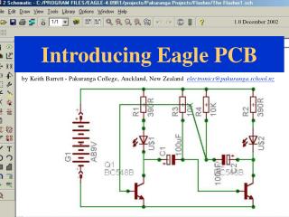
PCB DESIGNcon CadSoft EAGLE 4.1 lgiulianelli@arces.unibo.it
1. SCHEMATICO • connessione logica tra componenti • distribuzione di alimentazione e massa • 2. LAYOUT • disposizione fisica dei componenti (placing) • disposizione fisica delle connessioni (routing) • generazione output per manufacturing (gerber files) CONCETTI DI BASE
DISPOSITIVI ALIMENTAZIONE e MASSA CONNESSIONI SEMPLICI BUS Disposizione dei componenti puramente logica SCHEMATICO
CONTROLLO CORRETTEZZA DELLE CONNESSIONI ERC: Electrical Rule Check SCHEMATICO N.B. : Mai chiudere lo Schematico mentre si lavora sul Layout Perdita di coerenza NOTA: ERC è IN GRADO DI TROVARE SOLO LA CAUSA DI POSSIBILI ERRORI. STA A NOI INTERPRETARE CORRETTAMENTE I MESSAGGI D’ERRORE
piano di massa digitale(DGND) microcontrollore piano di massa analogica (AGND) amplificatore convertitore D/A connettore alimentazione uscita x cuffie • TOP layer • BOTTOM layer LAYOUT
CONTROLLO CORRETTEZZA DRC: Design Rule Check LAYOUT Il comando DRC controlla che il LAYOUT sia compatibile con i parametri tecnologici di progetto (design rules), dettati dal manufacturer.
DOVE SI TROVA? È POSSIBILE SCARICARE GRATUITAMENTE LA VERSIONE “LIGHT EDITION” AGGIORNATA DAL SITO : www.cadsoftusa.com Cadsoft EAGLE Restrizioni della LIGHT EDITION : • dimensione massima PCB = 100 x 80 mm al di fuori di questa area non è possibile posizionare componenti, né disegnare piste • numero massimo di layer = 2 non sono disponibili i layer interni • lo schematico deve essere contenuto in un unico foglio (single sheet)
CONVERTITORE D / A USCITA AUDIO CONVERSIONE DI UN SEGNALE DIGITALE ANALOGICO CON USCITA AUDIO ESERCIZIO MICROCONTROLLORE
COMPONENTI NECESSARI ESERCIZIO
PART LIST ESERCIZIO