Download
1 / 27
510 likes | 1.07k Views
Unit No. 03 Data Acquisition System. Presented by Prof. N. V. Avhad. Data Acquisition System.

E N D
Unit No. 03Data Acquisition System Presented by Prof. N. V. Avhad
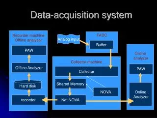
Data Acquisition System • Data acquisition is the process of sampling signals that measure real world physical conditions and converting the resulting samples into digital numeric values that can be manipulated by a computer. • Data acquisition systems typically measures an electrical & physical phenomenon and converts the analog waveforms into digital values for processing. • The data acquisition systems include: - Acquiring raw data from process - Converting it into usable units - Putting it into a form that can be displayed
It includes.. • Raw data acquisition- Data collection and acquisition is either time based/ Event based. • Time based- all data is gathered at predetermined time • Event based- collect data values based on some event • Transformation of Data- • Data Display-
Single Channel DAS • The components of data acquisition systems include: -Sensors, to convert physical parameters to electrical signals. -Signal conditioning circuitry, to convert sensor signals into a form that can be converted to digital values. -Analog-to-digital converters, to convert conditioned sensor signals to digital values.
Elements of Multichannel DAS • Transducers • Signal Conditioning Equipment • Multiplexer • Calibrating Equipment • Display Equipment
Multiplexer • It is the process of sharing a single channel with more than one output • It accepts multiple analog inputs and connects them sequentially to any one output line • ie. Using common transmission channel for transmitting more then one quantity • By Multiplexing cost of transmission and maintenance is reduced
Computer based DAS • Computer is equipped with additional hardware for data acquisition and analysis. Also suitable software for data acquisition is loaded. • The software includes programs for accessing the data, perform computations and to display the result. • The data acquisition hardware is a multifunction card, it accepts input analog voltage. This analog voltage is amplified to a standard level and then digitized by a high speed ADC.
Configuration of DAS Various significant factors are to be considered while selecting a data acquisition system- • Accuracy and resolution • No. of channels (single/multiple) • Sampling rate per channel • Signal conditioning for each channel • Analog or digital signals • cost
Objectives of DAS • To acquire necessary data at correct speed and correct time. • To use all the received data efficiently. • To monitor complete plant operation. • To collect, summarize and store data for diagnosis and record.
Applications of DAS • It is used for collecting information • It is used to convert the data into a useful form • It is used to generate information for display • DAS is used in aircraft control system, Electrical power generation, Industrial process system
Temperature control using DAS • The block diagram shows the processes that are to be carried out in order to control the temperature. • The temperature sensor first senses the temperature around it and gives out a corresponding voltage, which is amplified by the amplifier. • Amplified voltage then goes to the input to DAS • Amplified voltage is read by DAS software and analysis is made and other manipulation are added so as to provide control logic. • Output terminal of the DAS are given to 3 relays which operates Fan, pump motor and heater.
Bit width • When analog signal is converted to digital, it is represented in digital form by a series of binary number, each of which represent the signal value. • Thus, the number of binary digits or bits in each word is known as the bit width. • As the more bits the more precisely the binary numbers can represent the signal.
Aliasing • In signal processing, aliasing is an effect that causes different signal to become indistinguishable when sampled. • The original signal is reproduced at a wrong frequency this phenomenon is called aliasing. • It occurs when a system is measured at an insufficient sampling rate.
Sampling the data • DAS inputs the data from each transducer one at a time. It takes few milliseconds to input the data from one transducer connected to one channel. • Thus for a number of channels it will take certain time. This is called scanning. • The number of times inputting of the data or scanning is done is called as sampling rate or sampling frequency.
Sampling rate • The number of times inputting of the data or scanning is done is called as sampling rate. • If the values of these data coming from various transducers is changing with respect to time, then to get variation with time correctly the sampling rate has to be high. ie. Sampling has to be done very fast. • Eg. If data is changing at a frequency n Hz, then sampling frequency has to be equal to or greater than n.
Nyquist Sampling Theorem • As per this theorem, if the complete variation of a signal of frequency n with respect to time is to be correctly obtained by sampling then the sampling rate has to be at least 2n. This is called as Nyquist rate. • It is the rate at which an analog signal should be sampled so that it can be faithfully reproduced. As per Nyquist theorem, the sampling rate should be twice as fast as highest frequency of signal being measured or sampled.
Sample and Hold Circuit It consists of two steps- Sample-During sampling measured value of physical variable is given to the input module of DAS. This value is converted to a digital output and given to CPU for processing. Hold-This measured value of data sampled at the instant will be held in memory till the next sampling.
Role of S/H Circuit • Sample and hold circuit are used to sample or monitor the value of a voltage at frequent conditions. • The sampled value is held till such time it is again sampled. • The sampled voltage is stored in a capacitor by charging it. Hence name sample and hold.
Analog to Digital Converter (ADC) • A/D converter is a device that converts a continuous physical quantity (analog signal) to a digital number that represents the quantity's amplitude. • To convert an analog signal to digital the time axis has to be divided into a number of equally spaced interval. This process is known as Quantization. • Types- a) Flash type ADC b) Counter / ramp type ADC c) Successive approximation ADC
Successive Approximation ADC • Voltage comparator compares analog input voltage with output of DAC. The comparator is followed by successive approximation register (SAR). • SAR is used to find the required value of each bit by trial and error. • Analog input signal is applied & start command is given now SAR sets the MSB D1=1 with all other bits to 0. • If VA > Vx, The MSB is left at ‘1’ and next LSB is made ‘1’ and further tested. • If VA < Vx, The MSB is resettedto ‘0’ and go on to the next LSB and further tested.
Digital to Analog Converter (DAC) • D/A converter takes a digital code (binary signal) as its input and produces an analog voltage or current as its output. This analog output is proportional to the digital input. • The output voltage of DAC is given as Vo = KvVref ( b12-1 + b2 2-2 +........+ bn2-n ) • Types- a) Weighted resistor type DAC b) R-2R ladder type DAC
R-2R Ladder type ADC • It utilizes resistors of two values ie. R and 2R • The arrangement of resistors are such that the resistance looking into any of the nodes is a uniform value R, with a terminating resistance 2R. • The binary inputs are applied through switches. • Input current to op-amp by binary input is directly proportional to their digit weights. I1 = Vr / 2R, I2 = Vr/2/2R = Vr/4R …..and so on So the corresponding analog signals are produced as output.