Download
1 / 51
510 likes | 621 Views
Shape-from-Polarimetry: A New Tool for Studying the Air-Sea Interface. Howard Schultz, UMass Amherst, Dept of Computer Science Chris J. Zappa, Michael L. Banner, Russel Morison, Larry Pezzaniti. Introduction. Introduction. What is Polarimetry Light has 3 basic qualities

E N D
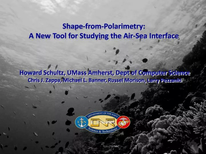
Shape-from-Polarimetry: A New Tool for Studying the Air-Sea Interface Howard Schultz, UMass Amherst, Dept of Computer Science Chris J. Zappa, Michael L. Banner,Russel Morison, Larry Pezzaniti
Introduction • What is Polarimetry • Light has 3 basic qualities • Color, intensity and polarization • Humans do not see polarization
Linear Polarization http://www.enzim.hu/~szia/cddemo/edemo0.htm
Amount of circular polarization Orientation and degree of linear polarization Intensity Muller Calculus • A bundle of light rays is characterized by intensity, a frequency distribution (color), and a polarization distribution • Polarization distribution is characterized by Stokes parameters S = (S0, S1, S2, S3) • The change in polarization on scattering is described by Muller Calculus SOUT = M SIN • Where M contains information about the shape and material properties of the scattering media • The goal: Measure SOUT and SIN and infer the parameters of M Incident Light Muller Matrix Scattered Light
Shape-from-Polarimetry (SFP) • Use the change in polarization of reflected or refractedskylight to infer the 2D surface slope, , for every pixel in the imaging polarimeter’s field-of-view
Shape-from-Polarimetry S = SAW + SWA SAW = RAWSSKYand SWA = TAWSUP Kattawar, G. W., and C. N. Adams (1989), “Stokes vector calculations of the submarine light-field in an atmosphere-ocean with scattering according to a Rayleigh phase matrix - Effect of interface refractive-index on radiance and polarization,” Limnol. Oceanogr., 34(8),1453-1472.
Shape-from-Polarimetry • For simplicity we incorporated 3 simplifying assumptions • Skylight is unpolarized SSKY = SSKY(1,0,0,0) good for overcast days • In deep, clear water upwelling light can be neglected SWA = (0,0,0,0). • The surface is smooth within the pixel field-of-view
Shape-from-Polarimetry Sensitivity = (DOLP) / θ
Experiments • Conduct a feasibility study • Rented a linear imaging polarimeter • Laboratory experiment • setup a small 1m x 1m wavetank • Used unpolarized light • Used wire gauge to simultaneously measure wave profile • Field experiment • Collected data from a boat dock • Overcast sky (unpolarized) • Used a laser slope gauge
Looking at 90 to the waves Looking at 45 to the waves Looking at 0 to the waves
X-Component Y-Component Slope in Degrees
X-Component Y-Component Slope in Degrees
Build an Imaging Polarimeter for Oceanographic Applications – Polaris Sensor Technologies • Funded by an ONR DURIP • Frame rate 60 Hz • Shutter speed as short as 10 μsec • Measure all Stokes parameters • Rugged and light weight • Deploy in the Radiance in a Dynamic Ocean (RaDyO) research initiative http://www.opl.ucsb.edu/radyo/
Camera 3 Camera 4 Camera 1 (fixed) Polarizing beamsplitter assembly Objective Assembly Camera 2 Motorized Stage 12mm travel 5mm/sec max speed
Deployed during the ONR experiment Radiance in a Dynamic Ocean (RaDyO) Scanning Altimeters and Visible Camera Air-Sea Flux Package ~36° Imaging Polarimeter
Analysis & Conclusion • A sample dataset from the Santa Barbara Channel experiment was analyzed • Video 1 shows the x- and y-slope arrays for 1100 frames • Video 2 shows the recovered surface (made by integrating the slopes) for the first 500 frames
Convert slope arrays to a height array Use the Fourier derivative theorem
Analysis & Conclusion • The shape-from-polarimetry method works well for small waves in the 1mm to 10cm range. • Need to improve the theory by removing the three simplifying assumptions • Skylight is unpolarized SSKY = SSKY(1,0,0,0) • Upwelling light can be neglected SWA = (0,0,0,0). • The surface is smooth within the pixel field-of-view • Needs to have an independent estimate of lower frequency waves.
Seeing Through Waves • Sub-surface to surface imaging • Surface to sub-surface imaging
Optical Flattening • Remove the optic distortion caused by surface waves to make it appear as if the ocean surface was flat • Use the 2D surface slope field to find the refracted direction for each image pixel • Refraction provides sufficient information to compensate for surface wave distortion • Real-time processing
Image FormationSubsurface-to-surface Observation Rays Air Water Imaging Array Exposure Center
Image Formationsurface-to-subsurface Exposure Center Imaging Array Air Imaging Array Water Exposure Center
Seeing Through Waves 0 20 40 60 80 0 10 20 30 40
Optical Flattening • Remove the optic distortion caused by surface waves to make it appear as if the ocean surface was flat • Use the 2D surface slope field to find the refracted direction for each image pixel • Refraction provides sufficient information to compensate for surface wave distortion • Real-time processing
Un-distortionA lens maps incidence angle θ to image position X θ Lens Imaging Array X
Un-distortionA lens maps incidence angle θ to image position X θ Lens Imaging Array X
Un-distortionA lens maps incidence angle θ to image position X Lens Imaging Array X
Un-distortionA lens maps incidence angle θ to image position X θ Lens Imaging Array X
Un-distortionA lens maps incidence angle θ to image position X θ Lens Imaging Array X
Un-distortionUse the refraction angle to “straighten out” light rays Image array Air Water Distorted Image Point
Un-distortionUse the refraction angle to “straighten out” light rays Image array Air Water Un-distorted Image Point
Real-time Un-Distortion • The following steps are taken Real-time Capable • Collect Polarimetric Images ✔ • Convert to Stokes Parameters ✔ • Compute Slopes (Muller Calculus) ✔ • Refract Rays (Lookup Table) ✔ • Remap Rays to Correct Pixel ✔
Image Formationsurface-to-subsurface Exposure Center Imaging Array Air Imaging Array Water Exposure Center
Detecting Submerged Objects“Lucky Imaging” • Use refraction information to keep track of where each pixel (in each video frame) was looking in the water column • Build up a unified view of the underwater environment over several video frames • Save rays that refract toward the target area • Reject rays that refract away from the target area