Download
1 / 20
200 likes | 418 Views
Achievements & Perspectives of MIMOSA Sensors (MAPS) for Vertexing Applications Christine Hu-Guo (IPHC) on behalf of IPHC (Strasbourg) & IRFU (Saclay) collaboration. Outline Achieved MAPS (Monolithic Active Pixel Sensors) performances R&D for improving MAPS performances

E N D
Achievements & Perspectives of MIMOSA Sensors (MAPS) for Vertexing ApplicationsChristine Hu-Guo (IPHC)on behalf of IPHC (Strasbourg) & IRFU (Saclay) collaboration Outline • Achieved MAPS (Monolithic Active Pixel Sensors)performances • R&D for improving MAPS performances • Increase readout speed Fast readout architecture • Applications and perspectives • Improve radiation tolerance • Projection beyond present (2D sensors) & perspectives • Conclusion
Development of MAPS for Charged Particle Tracking • In 1999, the IPHC CMOS sensor group proposed the first CMOS pixel sensor (MAPS) for future vertex detectors (ILC) • Numerous other applications of MAPS have emerged since then • ~10-15 HEP groups in the USA & Europe are presently active in MAPS R&D • Original aspect: integrate sensitive volume (EPI layer) and front-end readout electronics on the same substrate • Charge created in EPI, excess carries propagate thermally, collected by NWELL/PEPI , with help of reflection on boundaries with P-well and substrate (high doping) • Q = 80 e-h / µm signal < 1000 e- • Compact, flexible • EPI layer ~10–15 µm thick • thinning to ~30–40 µm permitted • Standard CMOS fabrication technology • Cheap, fast multi-project run turn-around • Room temperature operation • Attractive balance between granularity, material budget, radiation tolerance, read out speed and power dissipation • BUT • Very thin sensitive volume impacts signal magnitude (mV!) • Sensitive volume almost un-depleted impacts radiation tolerance & speed • Commercial fabrication (parameters) impacts sensing performances & radiation tolerance • NWELL used for charge collection restricts use of PMOS transistors R.T. IRFU - IPHC christine.hu@ires.in2p3.fr
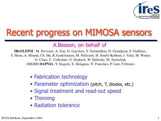
MIMOTEL M18 MIMOSTAR Chip dimension: ~2 cm² LUSIPHER Achieved Performances with Analogue Readout • MAPS provide excellent tracking performances • Detection efficiency ~100% • ENC ~10-15 e- • S/N > 20-30 (MPV) at room temperature • Single point resolution ~ µm, a function of pixel pitch • ~ 1 µm (10 µm pitch), ~ 3 µm (40 µm pitch) MAPS: Final chips: • MIMOTEL (2006): ~66 mm², 65k pixels, 30 µm pitch EUDET Beam Telescope (BT) demonstrator • MIMOSA18 (2006): ~37 mm², 262k pixels, 10 µm pitch High resolution EUDET BT demonstrator • MIMOSTAR (2006): ~2 cm², 204k pixels, 30 µm pitch Test sensor for STAR Vx detector upgrade • LUSIPHER (2007): ~40 mm², 320k pixels, 10 µm pitch Electron-Bombarded CMOS for photon and radiation imaging detectors IRFU - IPHC christine.hu@ires.in2p3.fr
Radiation tolerance (preliminary) • Ionising radiation tolerance: • O(1 M Rad) (MIMOSA15, test cond. 5 GeV e-, T = -20°C, tint~180 µs) • tint << 1 ms, crucial at room temperature • Non ionising radiation tolerance: depends on pixel pitch: • 20 µm pitch:2x10¹² neq /cm2, (Mimosa15, tested on DESY e- beams, T = - 20°C, tint ~700 μs) • 5.8·1012neq/cm² values derived with standardand with soft cuts • 10 µm pitch:1013 neq /cm2, (MIMOSA18, tested at CERN-SPS , T = - 20°C, tint ~ 3 ms) • parasitic 1–2 kGy gas N ↑ • Further studies needed : • Tolerance vs diode size, Readout speed, Digital output, ... , Annealing ?? IRFU - IPHC christine.hu@ires.in2p3.fr
System integration • Industrial thinning(via STAR collaboration at LBNL) • ~50 µm, expected to ~30-40 µm • Ex. MIMOSA18 (5.5×5.5 mm² thinned to 50 μm) • Development of ladder equipped with MIMOSA chips (coll. with LBNL) • STAR ladder (~< 0.3 % X0 ) ILC (<0.2 % X0 ) • Edgeless dicing / stitching alleviate material budget of flex cable IRFU - IPHC christine.hu@ires.in2p3.fr
MIMOSA22 Pixel Array Analogue processing / pixel Pixel array 136 x 576 pitch 18.4 µm 128 discriminators SUZE-01 A/D: 1 ADC ending each column Zero suppression Bias DC-DC Data transmission 5-bit ADC MAPS performance Improvement R&D organisation : 4 (5) simultaneous prototyping lines Architecture of pixel array organised in // columns read out: • Pre-amp and CDS in each pixel • A/D: 1 discriminator / column (offset compensation) • Power vs Speed • Power Readout in a rolling shutter mode • Speed Pixels belonging to the same row are read out simultaneously • MIMOSA8 (2004), MIMOSA16 (2006), MIMOSA22 (2007/08) Zero suppression circuit: Reduce the raw data flow of MAPS Data compression factor ranging from 10 to 1000, depending on the hit density per frame SUZE-01 (2007) 4–5 bits ADCs (~103 ADC per sensor) Potentially replacing column-leveldiscriminators 5 bits: sp ~1.7–1.6 µm 4 bits: sp < 2 µm for 20 µm pitch Next step: integrate column-level ADC with pixel array Serial link transmission with clock recovery Prototype (2008-2009) Voltage regulator & DC-DC converter IRFU - IPHC christine.hu@ires.in2p3.fr
0.64 mV 0.22 mV MIMOSA22 + SUZE-01 Test Results • MIMOSA22: (15 µm EPI) 136 x 576 pixels + 128 column-level discriminators • SUZE-01: • Lab. test : • Design performances reproduced up to 1.15 × design read-out frequency (115 MHz at room Temp ): • No pattern encoding error, can handle > 100 hits/frame at rate ~200 ns per pixel row • Still to do : improve radiation tolerance (SEU, SEL) of digital circuits (including memories) • Laboratory test: • Temporal Noise: 0.64 mV 12 e- • FPN: 0.22 mV 4 e- • Beam test at CERN SPS (120 GeV pions) • Threshold ~ 4 mV 6 x σ noise • Detection Efficiency > 99.5% • Single point resolution < 4 µm • Fake rate < 10-4 IRFU - IPHC christine.hu@ires.in2p3.fr
MIMOSA26: 1st MAPS with Integrated Ø CMOS 0.35 µm OPTO technology, Chip size : 13.7 x 21.5 mm2 • Pixel array: 576 x 1152, pitch: 18.4 µm • Active area: ~10.6 x 21.2 mm2 • In each pixel: • Amplification • CDS (Correlated Double Sampling) • Integration time: ~ 100 µs R.O. speed: 10k frames/s • Hit density: ~ 106 particles/cm²/s • Testability: several test points implemented all along readout path • Pixels out (analogue) • Discriminators • Zero suppression • Signal transmission Row sequencer Width: ~350 µm • 1152 column-level discriminators • offset compensated high gain preamplifier followedby latch Zero suppression logic Reference Voltages Buffering for 1152 discriminators I/O PadsPower supply PadsCircuit control PadsLVDS Tx & Rx Current Ref. Bias DACs Readout controller JTAG controller Memory management Memory IP blocks PLL, 8b/10b optional IRFU - IPHC christine.hu@ires.in2p3.fr
Test MIMOSA26 (Lab. + beam test) • Measured temporal noise = 0.6-0.7 mV and FPN = 0.3-0.4 mV for pixel array with its associated discriminators. • These values are equivalent to those obtained with Mimosa22. • It shows a good uniformity of the whole 576 x 1152 pixels with the 1152 discriminators • ~ 30 MIMOSA26 chips are tested (only 1 "dead") • The characterization of Mimosa26 is complemented by the beam tests (Sept. 2009) • 6 MIMOSA26 chips running simultaneously at nominal speed • Tracking successful • data analysis is underway, preliminary results show similar performances as MIMOSA22 IRFU - IPHC christine.hu@ires.in2p3.fr
y z x MIMOSA26 = Final Sensor for EUDET Beam Telescope • EUDET supported by the European Union in the 6th Framework Programme • Provide to the scientific community an infrastructure aiming to support the detector R&D for the ILC • JRA1 (Joint Research Activity): High resolution pixel beam telescope (BT) • Two arms each equipped with three layers of pixel sensors (MIMOSA) • DUT is located between these arms and moveable via X-Y table • EUDET beam telescope specifications: • High extrapolated resolution < 2 µm • Large sensor area ~ 2 cm2 • High read-out speed ~ 10 k frame/s • Hit density: up to 106 hits/s/cm2 Pixel Sensor MIMOSA26 13.7 mm (DUT) 21.5 mm Being Mounted on EUDET beam telescope Preliminary test results from the EUDET collaboration: • 3 MIMOSA26 chips mounted as DUT in BT demonstrator in July • BT tracks reconstructed in the 3 planes residues compatible with σsp ~ 3.5-4 μm IRFU - IPHC christine.hu@ires.in2p3.fr
Extension of MIMOSA-26 to STAR • Final HFT (Heavy Flavour Tracker) - PIXEL sensor : • MIMOSA-26 with active surface × ~1.7 • 1088 col. of 1024 pixels 1.1 million pixels • Pitch : 18.4 μm (~20.0 x 18.8 mm²) • Integration time 200 μs • Design from now fab. Feb. 2010 • 1st physics data expected in 2011/12 • Critical points: • Reduction of power consumption • Radiation tolerance improvement Also: • Integrated voltage reference • High speed transmission Pixel Vx Detector ~22.4 mm Inner Layer: 10 ladders Outer Layer: 30 ladders 10 sensors / ladder ~20.4 mm STAR Detector Upgrade IRFU - IPHC christine.hu@ires.in2p3.fr
Extension of MIMOSA-26 to CBM/FAIR & ILC • Micro Vertex Detector (MVD) of the CBM H.I. fixed target expt : • 2 double-sided stations equipped with MIMOSA sensors • MIMOSA-26 with double-sided read-out readout speed ! • Active surface : 2 x 1152 columns of 256 pixels • 21.2 x 9.4 mm2 • tint. ~ 40 μs • < 25 μs in < 0.18 μm techno. • Prototyping until 2012 start of physics in 2013/14 (?) • Vertex detector of the ILC: • tint. ~ 25 μs (innermost layer) double-sided readout • tint. ~ 100 μs (outer layer) Single-sided readout • 2 μm (4-bit ADC, 20 µm) < sp < 3 μm (discri. 14 µm pitch) • Pdiss < 0.1–1 W/cm² × 1/50 duty cycle ILD design: 2 options • Critical points: • Power pulsing • Design for the innermost layer: • Small pixel pitch • Faster readout speed 3 double layers 5 single layers IRFU - IPHC christine.hu@ires.in2p3.fr
Radiation Tolerance Improvement • Ionising radiation tolerance1. Special layout • Diode level (already realized): Remove thick oxide surrounding N-well diode by replacing with thin-oxide without design rule violation!! • Pixel circuit level: ELT for the transistors connected to the detection diode 2. Minimise integration time Increase readout speed: Minimise leakage current IRFU - IPHC christine.hu@ires.in2p3.fr
Radiation Tolerance Improvement • Non ionising radiation toleranceHigh resistivity sensitive volume faster charge collection • Exploration of a VDSM technology with depleted (partially ~30 µm) substrate: • Project "LePix" driven by CERN for SLHC trackers (attractive for CBM, ILC and CLIC Vx Det.) • Exploration of a technology with high resistivity thin epitaxial layer • XFAB 0.6 µm techno: ~15 µm EPI ( ~ O(103).cm), Vdd = 5 V (MIMOSA25) Benefit from the need of industry for improvement of the photo-sensing elements embedded into CMOS chip TCAD Simulation 15 µm high resistivity EPI compared to 15 µm standard EPI For comparison: standard CMOS technology, low resistivity P-epi high resistivity P-epi: size of depletion zone size is comparable to the P-epi thickness! IRFU - IPHC christine.hu@ires.in2p3.fr
Landau MP (in electrons) versus cluster size 0 neq/cm² 0.3 x 10¹³ neq/cm² 1.3 x 10¹³ neq/cm² 3 x 10¹³ neq/cm² MIMOSA25 in a high resistivity epitaxial layer • 20 μm pitch, + 20°C, self-bias diode @ 4.5 V, 160 μs read-out time • Fluence ~ (0.3 / 1.3 / 3·)1013 neq/cm2 • Tolerance improved by > 1 order of mag. • Need to confirm det (uniformity !) with beam tests MIMOSA25 saturation -> >90 % of charge is collected is 3 pixels -> very low charge spread for depleted substrate 16x96 Pitch 20µm To compare: «standard» non-depleted EPI substrate: MIMOSA15 Pitch=20µm, before and after 5.8x10¹² neq/cm2 IRFU - IPHC christine.hu@ires.in2p3.fr
Analog Readout Circuit Analog Readout Circuit Analog Readout Circuit Analog Readout Circuit Diode Diode Diode Diode digital process (number of metal layers)feature size fast laser driver, etc. 3D - MAPS 2D - MAPS Pixel Controller, A/D conversion Digital Analog ~ 50 µm Pixel Controller, CDS Sensor TSV: Through Silicon Vias ~ 20 µm Using 3DIT to improve MAPS performances • 3DIT are expected to be particularly beneficial for MAPS : • Combine different fabrication processes • Resorb most limitations specific to 2D MAPS • Split signal collection and processing functionalities, use best suited technology for each Tier : • Tier-1: charge collection system Epitaxy (depleted or not), deep N-well ? ultra thin layer X0 • Tier-2: analogue signal processing analogue, low Ileak, process (number of metal layers) • Tier-3: mixed and digital signal processing • Tier-4: data formatting (electro-optical conversion ?) • Run in Chartered - Tezzaron technology • 130 nm, 2-Tier run with "high"-res substrate (allows m.i.p. detection) • Tier A to tier B bond Cu-Cu bond • 3 D consortium: coordinated by FermiLab • FermiLab • INFN • IN2P3-IRFU • Univ. of Bonn • CMP IRFU - IPHC christine.hu@ires.in2p3.fr
Acquisition Readout ~1 ms ~200 ms ~1 ms Tier 1 Tier 2 A B TS & R.O. Detection diode or Q injection Amplifier Amp.+Shaper Discriminator Hit identification 5 bits (7?) Time Stamp 2nd hit flag ReadOut ASD + 12 µm 12 µm Detection diode & Amp 24 µm IPHC & IRFU 3D MAPS • Delayed R.O. Architecture for the ILC Vertex Detector • Try 3D architecture based on small pixel pitch, motivated by : • Single point resolution < 3 μm with binary output • Probability of > 1 hit per train << 10 % • 12 μm pitch : • sp ~ 2.5 μm • Probability of > 1 hit/train < 5 % • Split signal collection and processing functionalities : • Tier-1: A: sensing diode & amplifier, B: shaper & discriminator • Tier-2: time stamp (5 bits) + overflow bit & delayed readout Architecture prepares for 3-Tier perspectives : 12 µm • Tier-1: CMOS process adapted to charge collection • Tier-2: CMOS process adapted to analogue & mixed signal processing • Tier-3: digital process (<< 100 nm ????) IRFU - IPHC christine.hu@ires.in2p3.fr
Tier-1 Tier-2 Tier-3 off <10 mV Cf~10fF G~1 Digital RD Cc=100fF Vth Cd~10fF Tezzaron (metal-metal (Cu) thermocompression) Ziptronix (Direct Bond Interconnect, DBI®*) IPHC 3D MAPS: Self Triggering Pixel Strip-like Tracker (STriPSeT) • Combine Tezzaron/Chartered 2-tiers process with XFAB high resistivity EPI process • Tier-1: XFAB, 15 µm depleted epitaxy ultra thin sensor!!! • Fully depleted Fast charge collection (~5ns) should be radiation tolerant • For small pitch, charge contained in less than two pixels • Sufficient (rather good) S/N ratio defined by the first stage • “charge amplification” ( >x10) by capacitive coupling to the second stage • Tier-2: Shaperless front-end: (Pavia + Bergamo) • Single stage, high gain, folded cascode based charge amplifier, with a current source in the feedback loop Shaping time of ~200 ns very convenient: good time resolution • Low offset, continuous discriminator • Tier-3: Digital: Data driven (self-triggering), sparsified binary readout, X and Y projection of hit pixels pattern • Matrix 256x256 2 µs readout time • DBI® – Direct Bond Interconnect, low temperature CMOS compatible direct oxide bonding with scalable interconnect for highest density 3D interconnections (< 1 µm Pitch, > 108/cm /cm² Possible) IRFU - IPHC christine.hu@ires.in2p3.fr
Digital Memory and Digital Readout LATCH_D DREAD Discriminator Tier-2 Tier-1 IRFU & IPHC 3D MAPS: RSBPix • FAST R.O. architecture aiming to minimise power consumption • Subdivide sensitive area in ”small” matrices running INDIVIDUALLY in rolling shutter mode • Adapt the number of raws to required frame r.o. time few µs r.o. time may be reached (???) • Planned also to connect this 2 tier circuit to XFAB detector tier IRFU - IPHC christine.hu@ires.in2p3.fr
Conclusion • 2D MAPS have reached necessary prototyping maturity for real scale applications : • Beam telescopes allowing for sp ~ few μm & 106 particles/cm²/s • Vertex detectors requiring high resolution & very low material budget • The emergence of fabrication processes with depleted epitaxy / substrate opens the door to : • Substantial improvements in read-out speed and non-ionising radiation tolerance • "Large pitch" applications trackers (e.g. Super LHC ) • Translation to 3D integration technology : • Resorb most limitations specific to 2D MAPS • T type & density, peripheral insensitive zone, combination of different CMOS processes • Offer an improved read-out speed : O(μs) ! • Many difficulties to overcome (ex. heat, power) • R&D in progress 2009/10 important step for validation of this promising technology IRFU - IPHC christine.hu@ires.in2p3.fr