Download
1 / 24
551 likes | 2.22k Views
HEAT TRANSFER IN AGITATED VESSELS. HEAT TRANSFER IN AGITATED VESSELS. GROUP MEMBERS Nadeem Akhtar 2006-Chem-22 Zohaib Atiq Khan 2006-Chem-40. Problem Statement.

E N D
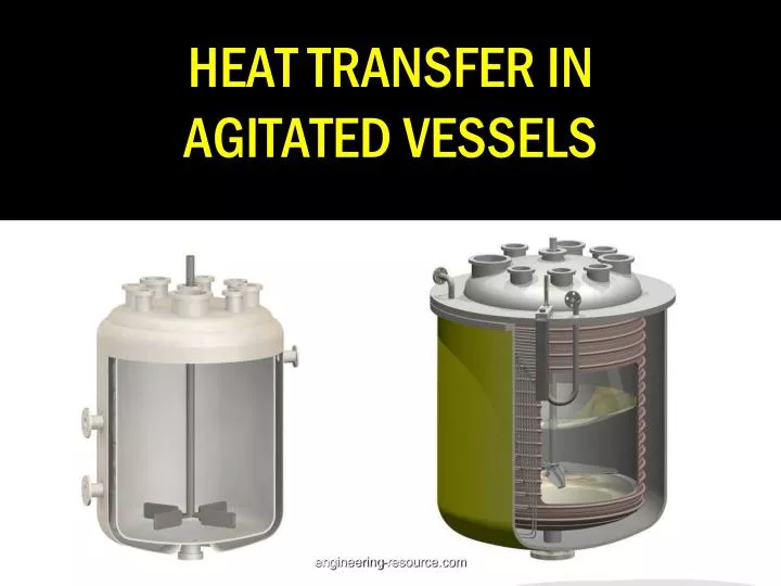
HEAT TRANSFER IN AGITATED VESSELS engineering-resource.com
HEAT TRANSFER IN AGITATED VESSELS GROUP MEMBERS NadeemAkhtar 2006-Chem-22 Zohaib Atiq Khan 2006-Chem-40 engineering-resource.com
Problem Statement A batch polymerization reactor, 1500mm in diameter and 1800 mm high, has a limpet coil of 18 turns. The inner diameter of the half-pipe is 52.5 mm and the pitch of the coil is 79.5 mm. In Each batch, 2200 kg of the monomer at 25 oC is charged to the reactor that has to be heated to 80 oC before the initiator is added to start the polymerization. engineering-resource.com
Problem Statement Heating is done by a hot fluid available at 1200C. The average viscosity of the hot fluid may be taken as 4 cP, and that of the monomer as 0.7 cP. The vessel is provided with a flat blade turbine agitator (six blade. 0.5 m diameter) which rotates at 150 rpm. engineering-resource.com
Problem Statement The volume of the charge is such that, the liquid surface remains nearly at the level of the top of the limpetted region . The height of the limpeted section = 1464 mm. A fouling factor of 0.0002 h m2oC/kcal may be taken for both the vessel and the coil side. Calculate the time required to heat the charge. engineering-resource.com
DATA: Reactor & Coil engineering-resource.com
DATA engineering-resource.com
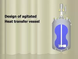
DATA: agitator FLAT BLADE TURBINE AGITATOR engineering-resource.com
SOLUTION STRATEGY 1-Calculate Internal Heat Transfer Area of the Vessel 2- Calculate the vessel-side heat transfer coefficient 3-Calculate Coil side Heat transfer coefficient engineering-resource.com
SOLUTION STRATEGY 4- Calculate Overall Heat Transfer coefficient 5- Calculate Time Required for Batch Heating engineering-resource.com
Inside heat transfer areaof the vessel The inside heat transfer area of the vessel Ai = DtH H = 1464mm Dt = 1500mm A = 6.9 m2 engineering-resource.com
VESSEL SIDE H.T COEFFICIENT • Agitator diameter = 0.5 m • Rpm. = 150 Equation for hi is hi = 0.74 x k x (Re)0.67 (Pr) 0.33 Dt engineering-resource.com
VESSEL SIDE H.T COEFFICIENT • Pr. (Prandtl no.) `= (0.45)(0.7 x 10⁻³)(3600) 0.15 = 7.56 Re.(Reynold no.) = d2Nρ = (0.5)2(150/60)(850) μ(0.7x10⁻³) = 7.59 x 10⁵ engineering-resource.com
VESSEL SIDE H.T COEFFICIENT • Putting the values of variables in the equation of hi hi = 0.74 x 0.15 x (7.59 x 105)0.67 (7.56) 0.33 1.5 = 1256 kcal / h m2 oC engineering-resource.com
COIL SIDE H.T COEFFICIENT Take the linear velocity of the heat transfer fluid = 1.5 m/s Flow area of the coil = (π/4)(0.0525)2 = 2.165 x 10⁻³ m2 Flow area of the fluid = (1.5)(2.165 x 10⁻³)(3600) = 11.69 m3/h Mass flow rate of the fluid = Wc=(11.69)(850) = 9936 kg/h engineering-resource.com
COIL SIDE HT COEFFICIENT Hydraulic diameter of the limpet coil, dH dH = (4)(π/8)(di)2 = π (0.0525) = 0.0321 m di + (π/2)di 2 + π Coil Reynolds Number Re = VdHρ = (1.5)(0.0321)(900) =10,820 μ 4 x 10⁻³ engineering-resource.com
COIL SIDE H.T COEFFICIENT Prandtl Number of the coil fluid Pr = Cpμ = (0.5)(4 x 10⁻³)(3600) =25.7 k 0.28 Coil side heat transfer coefficient deho = 0.027 x (Re)0.8 (Pr) 0.33 [1 + 3.5(de/dc)] k h0 = 1080 kcal/h m2 0C engineering-resource.com
Overall Heat Transfer Coefficient • U = 467 kcal /h m2 0 C engineering-resource.com
TIME REQUIRED • Given data is • Wc = 9936 kg/h • cpc = 0.5 kcal/kg OC • Wv = 2200 kg • cpv = 0.45 kcal/kg oC • inlet temperature of the coil fluid, Tci = 120 oC • initial temperature of the vessel liquid, Tvi = 25 oC. • final temperature, Tvf = 80oC engineering-resource.com
TIME REQUIRED Putting the values of the various quantities in, we get ln(T – t1/T – t2) = (WcCpc/WvCpv)((K – 1)/ K) K = exp(UiAi/Wccpc) = exp((467)(6.9)/(9936)(0.5)) = 1.913 ln(120-25/120-80 )= (9936)(0.5)/(2200)(0.45)(1.913-1/1.913) t t = 22mins engineering-resource.com
THANKS engineering-resource.com