Download
1 / 37
400 likes | 682 Views
Design of agitated Heat transfer vessel. GROUP MEMBERS SABA 06-CHEM-02 FARIHA 06-CHEM-16 SHAZIA 06-CHEM-38. Dual Shaft Paste Mixer.

E N D
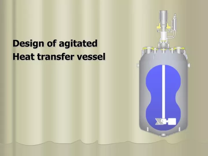
Design of agitated Heat transfer vessel
GROUP MEMBERS SABA 06-CHEM-02 FARIHA 06-CHEM-16 SHAZIA 06-CHEM-38
Dual ShaftPaste Mixer • The Dual Shaft Mixer includes an Anchor agitator and a High Speed Disperser. The anchor feeds product into the high speed disperser blade and ensures that the mixture is constantly in motion. The anchor can be provided with scrapers to remove materials from the interior vessel walls to enhance the heat transfer capabilities of the mixer. Both agitators are available for variable speed operation
Applications • Mixing tanks are typically used in the production of viscous fluids such as petroleum, plastics, paints, paper, cosmetics, and food. The mechanical agitation of fluid in these vessels can significantly increase the rate of heat transfer between the process and cooling fluids. Since the 1950s, a number of authors have explored heat transfer for Newtonian fluids in a variety of agitated vessel configurations. There has been a limited amount of research performed, however, for heat transfer to non-Newtonian (power law) fluids.
Petro-Chemical, Polymers,Coatings & Adhesives ,Agricultural & General Chemicals,Plastics&Rubber ,Food & Beverage Industry.
Homogeneous Batch/Semi-batch Reactions • Homogeneous batch/semi-batch are the most common reaction type. They can be as simple as adding measured quantities of two or more reactants to a vessel and mixing. Heat is normally removed or added through a jacket, heating mantle or external heat exchanger
STATEMENT Calculate the time required to heat 1268 gal. of liquid from 80OF to 180OF in a jacketed, agitated vessel conforming to standard configuration as shown in the figure. The vessel is assumed to be clean, free of fouling films and heated with 212OF steam.
Data Given Liquid Properties: Cp = 0.6 Btu/(lb) (OF) k= 0.1Btu/(hr)(sq.ft)(OF/ft) μ= 1000cp (at80F) ρ=60lb/ft3 = 8.02lb/gal Cp,k and ρ are assumed to be constant
Steam properties: hs=1000 Btu/(hr)(sq.ft)(OF) Vessel Properties: Wall thickness= 0.125 in K of vessel = 9.4 Btu/(hr)(sq.ft)(OF/ft) Eq used for calculating heat transfer coefficient NNU = 0.73(NRE)0.65(NPR)0.33(μw/ μb)0.14
STEP 1: Diameter of the vessel DT =6 ft. 6-ft diameter agitated vessel conforming to standard configuration as shown in the figure. The vessel is equipped with the 2 ft diameter 6-blade, flat-blade turbine impeller running at 100 rpm. Diameter of impeller = 2ft Impeller blade width=0.5 ft Impeller blade height=0.4 ft Baffle width=0.6 ft
STEP 2: Inside area of the vessel = πDL (L=D) = 3.14(6)(6) = 113 ft2
STEP 3: Reynolds number evaluation at 80F,130F,180F by using, NRE = ρN Di2/μ Here, we assume density to be constant over the temperature range. Viscosity values at different temperatures is; μ(80F) = 1000cp (from table) μ(130F) = 270 cp μ(130F) = 84cp
Diameter of impeller, Di = 2 ft From these values , the Reynolds number is, NRE(80F) = (60)(6000)(4)/(2420) = 595 NRE(130F)= 2200 NRE (130F)=7080
STEP 4: The Prandtl number calculations at 80F,130F,180F are, NPR = CPμ /k NPR (80F) = (0.6)(2420)/(0.1) = 14500 NPR (130F) = 3920 NPR (180F) = 1220
STEP 5: Approximate the value of inside heat transfer coefficient from given equation; NNU = hi DT/k = 0.73(NRE)0.65(NPR)0.33 substitutingthe appropriate values into this relationship gives: hi(80F) =18.4 Btu/(F) (hr) (sq.ft) hi(130F) =27.6 Btu/(F) (hr) (sq.ft) hi(180F) =40.4 Btu/(F) (hr) (sq.ft)
STEP 6: The wall temperature from the above heat transfer coefficients are calculated and used to evaluate the viscosity of liquid at vessel wall The wall temperature is estimated from the approximate equation: TW = TS – [(TS -TB)/1+(hsAO/hiAi)] here, AO= Ai
Solving wall temperature TW (at TB = 80F) = 209.6 F TW (at TB = 130F) = 209.8 F TW (at TB = 180F) = 210.7 F Viscosity values at different temperatures is; μ(209.6F) = 47cp (from table) μ(209.8F) = 47cp μ(210.7F) = 46 cp
Calculate the viscosities ratios equals to μw/ μb • At TB =80F and TW = 209.6F VIS=47/1000=0.047 • At TB =130F and TW = 209.8F VIS=47/270=0.174 • At TB =80F and TW = 209.6F VIS=46/85=0.541
STEP 7: NNU = 0.73(NRE)0.65(NPR)0.33(μw/ μb)0.14 As NNU = hi DT/k hi(80F) =38.4 Btu/(F) (hr) (sq.ft) hi(130F) =42.2 Btu/(F) (hr) (sq.ft) hi(180F) = 46.7Btu/(F) (hr) (sq.ft)
STEP 8: 1/Ui = 1/hi+ x/k +1/hs hi= as calculated in step 7 x= 1/8 in =0.0104 ft K= 9.4 Btu/(hr)(sq.ft)(F/ft) for the vessel wall hs= 1000 Btu/(F) (hr) (sq.ft) Ui(Tb=80 F) =0.0281 Btu/(F) (hr) (sq.ft) Ui(Tb=130 F) =38.7 Btu/(F) (hr) (sq.ft) Ui(Tb=180 F)= 42.5 Btu/(F) (hr) (sq.ft)
STEP 9: Time taken to heat the liq over each temp increment is calculated by this formula Thr=(MCP/UiAi) ln [TS – TI/TS –Tf] Liquid mass= π(Dt2/4)(Ht)(ρ) = π(36/4)(6)(60) =10180 lb
Time reqd to heat the nass from 80 to 100 F is calculated as t(80-100F) = (10180)(0.6) ln (212-80) (36.15)(113) (212-100) =0.242 hr t(100 -120F) = 0.283 hr t(120 -140F) = 0.340 hr t(140-160F) = 0.439 hr t(160-180F) =0.630 hr Total Time = 1.934 hr
Approximate method: Thr=(MCP/UiAi) ln [TS – TI/TS –Tf] Thr=(10180*0.6/38.7*113) *ln [212-80/212 -180] Thr=1.981 hr Value differ by only 2.4%