Download
1 / 1
10 likes | 105 Views
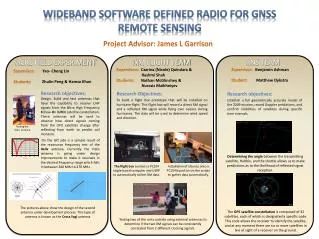
Advisors : Prof. J. L. Garrison, Prof . J. V. Krogmeier Graduate Mentor : Yao- C heng Lin Members: Sutton Hathorn , Zach Vander Missen. Wideband Software Defined Radio for Remote Sensing with Signals of Opportunity . Department of Electrical and Computer Engineering .

E N D
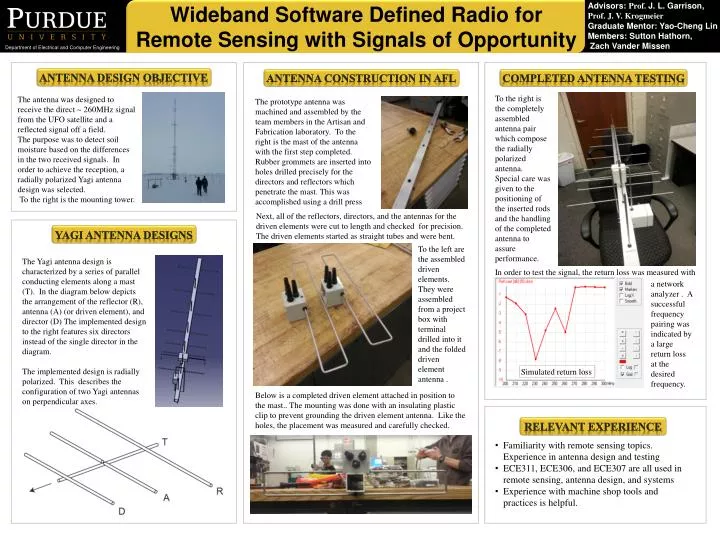
Advisors: Prof. J. L. Garrison, Prof. J. V. Krogmeier Graduate Mentor: Yao-Cheng Lin Members: Sutton Hathorn, Zach Vander Missen Wideband Software Defined Radio for Remote Sensing with Signals of Opportunity Department of Electrical and Computer Engineering Antenna Design Objective Antenna Construction in AFL Completed Antenna testing To the right is the completely assembled antenna pair which compose the radially polarized antenna. Special care was given to the positioning of the inserted rods and the handling of the completed antenna to assure performance. The antenna was designed to receive the direct ~ 260MHz signal from the UFO satellite and a reflected signal off a field. The purpose was to detect soil moisture based on the differences in the two received signals. In order to achieve the reception, a radially polarized Yagi antenna design was selected. To the right is the mounting tower. The prototype antenna was machined and assembled by the team members in the Artisan and Fabrication laboratory. To the right is the mast of the antenna with the first step completed. Rubber grommets are inserted into holes drilled precisely for the directors and reflectors which penetrate the mast. This was accomplished using a drill press Next, all of the reflectors, directors, and the antennas for the driven elements were cut to length and checked for precision. The driven elements started as straight tubes and were bent. Yagi Antenna Designs To the left are the assembled driven elements. They were assembled from a project box with terminal drilled into it and the folded driven element antenna . The Yagi antenna design is characterized by a series of parallel conducting elements along a mast (T). In the diagram below depicts the arrangement of the reflector (R), antenna (A) (or driven element), and director (D) The implemented design to the right features six directors instead of the single director in the diagram. The implemented design is radially polarized. This describes the configuration of two Yagi antennas on perpendicular axes. In order to test the signal, the return loss was measured with a network analyzer . A successful frequency pairing was indicated by a large return loss at the desired frequency. Simulated return loss Below is a completed driven element attached in position to the mast.. The mounting was done with an insulating plastic clip to prevent grounding the driven element antenna. Like the holes, the placement was measured and carefully checked. Relevant Experience • Familiarity with remote sensing topics. Experience in antenna design and testing • ECE311, ECE306, and ECE307 are all used in remote sensing, antenna design, and systems • Experience with machine shop tools and practices is helpful.