Download
1 / 1
10 likes | 85 Views
ACRE FIELD EXPERIMENT. RNS TEAM Supervisor: Benjamin Ashman Student: Matthew Dykstra. XM FLIGHT TEAM Supervisors: Czarina (Nicole) Quindara & Rashmi Shah Students: Nathan McGlinchey &

E N D
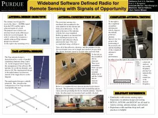
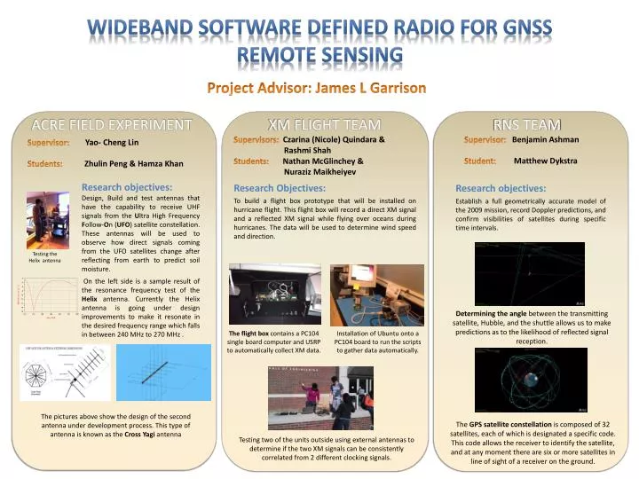
ACRE FIELD EXPERIMENT • RNS TEAM • Supervisor: Benjamin Ashman • Student: Matthew Dykstra • XM FLIGHT TEAM • Supervisors: Czarina (Nicole) Quindara & • Rashmi Shah • Students: Nathan McGlinchey & • NurazizMaikheiyev • Research Objectives: • To build a flight box prototype that will be installed on hurricane flight. This flight box will record a direct XM signal and a reflected XM signal while flying over oceans during hurricanes. The data will be used to determine wind speed and direction. • Supervisor: Yao- Cheng Lin • Students:ZhulinPeng & Hamza Khan Wideband software defined radio for GNSS Remote Sensing Research objectives: Establish a full geometrically accurate model of the 2009 mission, record Doppler predictions, and confirm visibilities of satellites during specific time intervals. Research objectives: Design, Build and test antennas that have the capability to receive UHF signals from the Ultra High Frequency Follow-On (UFO) satellite constellation. These antennas will be used to observe how direct signals coming from the UFO satellites change after reflecting from earth to predict soil moisture. On the left side is a sample result of the resonance frequency test of the Helix antenna. Currently the Helix antenna is going under design improvements to make it resonate in the desired frequency range which falls in between 240 MHz to 270 MHz . Testing the Helix antenna Project Advisor: James L Garrison Determining the angle between the transmitting satellite, Hubble, and the shuttle allows us to make predictions as to the likelihood of reflected signal reception. The flight box contains a PC104 single board computer and USRP to automatically collect XM data. Installation of Ubuntu onto a PC104 board to run the scripts to gather data automatically. The pictures above show the design of the second antenna under development process. This type of antenna is known as the Cross Yagiantenna The GPS satellite constellation is composed of 32 satellites, each of which is designated a specific code. This code allows the receiver to identify the satellite, and at any moment there are six or more satellites in line of sight of a receiver on the ground. Testing two of the units outside using external antennas to determine if the two XM signals can be consistently correlated from 2 different clocking signals.