Download

1 / 23
230 likes | 418 Views
Pulsed-Latch Aware Placement for Timing-Integrity Optimization. Yi-Lin Chuang1, Sangmin Kim2, Youngsoo Shin2, and Yao-Wen Chang National Taiwan University, Taiwan KAIST, Korea 2010 DAC. Outline. Introduction Preliminaries Problem Formulation Algorithm Experimental Results

E N D
Pulsed-Latch Aware Placement for Timing-Integrity Optimization Yi-Lin Chuang1, Sangmin Kim2, Youngsoo Shin2, and Yao-Wen Chang National Taiwan University, Taiwan KAIST, Korea 2010 DAC
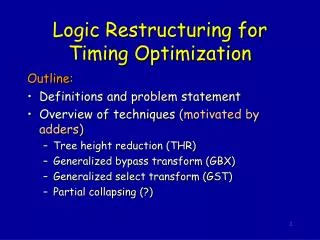
Outline • Introduction • Preliminaries • Problem Formulation • Algorithm • Experimental Results • Conclusion
Introduction • In the simulation report under the 45nm process technology from our experiments, a flip-flop requires 1.25X setup time and 1.55X area than a latch. • Flip-flops have significant overheads than latches in terms of delay, clock load, and area.
Introduction • Level-sensitive latch designs are relatively simple and consume much less power than that of flip-flops. • However, it is harder to perform timing verification on latch designs due to their data transparent nature.
Introduction • Pulsed latches are latches driven by a pulse clock waveform, and synchronized with the clock similarly to an edge-triggered flip-flop. • offers easier timing verification/optimization just like a flip-flop. • In recent research, by selecting appropriate pulse widths for each latch, we can effectively improve circuit timing [10]. • Pulsed-latch based designs have become a promising solution for modern circuit designs.
Introduction • Pulsed-latch circuit and pulse generator structure.
Introduction • The delay and driving capability of a pulse generator would also be affected by the (output) load capacitance. • If a pulse generator and latches are not placed properly, the wirelength among them might become too long and thus make the generated pulse width distorted.
Preliminaries-NTUplacer3 • We adopt NTUplace3 to demonstrate our placement flow. • The analytical placement optimizes wirelengthunder the cell density constraint which is modeled with uniform non-overlapping bins.
Preliminaries-Pulse-Generator Characteristics • HSPICE simulation
Problem Formulation • Pulsed-Latch Aware Placement: Given a pulsed-latch-width scheduled netlist, the maximum tolerable load capacitance of each type of generators, determine pulse-generator latches(PGL) groups and find a placement for blocks such that the total wirelength is minimized and specified maximum tolerable capacitance is also satisfied.
Algorithm • We propose a pulsed-latch aware multilevel analytical placement framework.
Pulsed-latch-width scheduled netlist[10] • Timing constraints of Pulsed Latch-Based Circuits
PGL-Macro-Like Clustering • The multilevel framework adopts a two-stage technique of bottom-up coarsening followed by top-down uncoarsening. • Since in the uncoarsening stage, each cluster contains multiple movable blocks, and the exact placement within a cluster remains unknown, it is relatively difficult to optimize PGL-group locations within each cluster directly. • Therefore, in the finest level after each PGL macro is declustered, the latches belonging to the same PGL group would have relatively closer distances.
PGL-Group Compression • To apply the log-barrier method, mathematically we need to start at a feasible initial solution, implying that the wirelengthof each PGL group should not exceed its constraint. • X is the original x-coordinate matrix of latches • diagis the diagonal matrix with diagonal entries (1−αi) • xgis the x-coordinate of generator • X’ is the resultant x-coordinate
PGL-Group-Aware Placement • Barrier Method for Pulsed-Latch-Aware Global Placement • By defining the logarithmic barrier, we solve a sequence of unconstrained minimization problems as follows:
Experimental Results • Placement algorithm was integrated into NTUplace3. • Mainly compare our proposed pulsed-latch aware placement flow with two placers, Cadence SOC Encounter [3] and DCTB [17] (a academic clock-tree aware placer). • Testcase: six OpenCores [13] circuits in the IWLS2005 benchmark suite. • A set of five pulse generators were constructed to provide pulse widths. The widths were 230ps, 322ps, 423ps, 522ps, and 623ps.
Experimental Results • Compare with three different flows: • (A)LC[10] (latch-clustering) followed by SOC Encounter • (B) LC followed by DCTB • (C)our proposed flow • After circuit placement, we used FLUTE to estimate the clock Steiner wirelength. • By the simulation results shown in Figure 3, we computed the corresponding pulse width by interpolation, and applied the derived pulse widths to latches for timing verification.
Experimental Results • To quantify this metric, we proposed the “Pulse Width Degradation Ratio” (PWDR) to model the width degradation of each latch.
Conclusion • We have introduced the pulsed-latch aware placement problem for timing integrity. • we have proposed a better latch-group determination algorithm considering physical information and have extended the analytical placement to reduce the potential load capacitance of pulse generators. • Experimental results have shown the effectiveness and efficiency of our approach for pulsed-latch placement.