Download
1 / 15
170 likes | 308 Views
Adaptive Optics Deformable Mirror Electronics Simulation. Pearl Yamaguchi Subaru Telescope National Astronomical Observatory of Japan Mentor: Stephen Colley. Outline. Project Scope Adaptive Optics Deformable Mirror Protecting the Deformable Mirror Determinations. Project Scope.

E N D
Adaptive Optics Deformable Mirror Electronics Simulation Pearl Yamaguchi Subaru Telescope National Astronomical Observatory of Japan Mentor: Stephen Colley
Outline • Project Scope • Adaptive Optics • Deformable Mirror • Protecting the Deformable Mirror • Determinations
Project Scope • Investigate ways of protecting the Deformable Mirror • From sharp changes in voltage • Slew rate limit • Concern • Possible damage due to rapid changes in drive signals
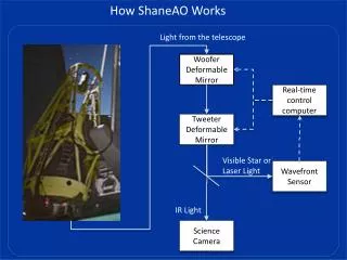
Adaptive Optics • Primary Components of AO System • Wavefront Sensor • Control Computer • Deformable Mirror Image without AO Image with AO
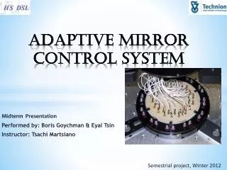
Bimorph Deformable Mirror • Two piezoelectric wafers • Oppositely polarized • Array of electrodes • Dynamically compensates for aberrations • Expanding or contracting with stimulus
Deformable Mirror Actuators • Current AO System 36 actuators • Second Generation AO 188 Actuators Electrode pattern • Inner and Outer segments • Load on electronics appears as pure capacitance
Project Objective • Manufacturer suggested slew rate limit 100 Volts/ms • Full scale range +/- 400 Volts • Ramping insures limit V 200V 100V 1ms 2 ms time
Protection from Voltage Jumps • Control Computer • Digital to Analog Converters • High Voltage Amplifiers Control Computer D/A Converter HV Amplifier DM Ideal safety feature here
High Voltage Amplifiers • Current Limiting to limit charging of segment • Capacitive Load • Non-Linear operation of amplifiers
Electronics Simulation for Deformable Mirror • Implemented and expanded circuit • Using PSpice • Models behavior of circuit elements • Time and frequency response • Test validity of design considerations
Current Limiting High Voltage Amplifiers Significant Results • Oscillates • Unstable • Eliminated as a solution
Digital to Analog Converters • Determine if digital logic implemented slew rate limit is feasible • Continue simulation of D/A Converters • Test step limited slew rate Control Computer D/A Converter HV Amplifier DM
Stepping Approximation • Approximate ramp with Stepping • Implement in digital logic • D/A Converters V 200V 100V 1ms 2 ms time
Summary • Protect the mirror • Created PSpice model • Ruled out High Voltage Amplifiers • Investigated D/A Converters V 200V 100V 1ms 2 ms time
Acknowledgements • Stephen Colley, AO Project Engineer • Hideki Takami, AO Project Manager • Subaru Telescope, NAOJ • Center for Adaptive Optics • University of Hawaii, Manoa This project is supported by the National Science Foundation Science and Technology Center for Adaptive Optics, managed by the University of California at Santa Cruz under cooperative agreement. No. AST - 9876783