Download
1 / 37
400 likes | 682 Views
Fiber Optics & Electronics. Security. Speed. A utomatic S ource T ransfer < 8 Cycles < 150ms. Build an asset. Fiber has a 20 year + life Any excess fiber can be leased or sold. Fiber Optic Glass Types. Multimode Fiber Large Core most common 62.5um Only good for < 4KM

E N D
Speed Automatic Source Transfer < 8 Cycles < 150ms
Build an asset • Fiber has a 20 year + life • Any excess fiber can be leased or sold
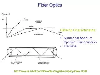
Fiber Optic Glass Types • Multimode Fiber • Large Core most common 62.5um • Only good for < 4KM • Single Mode Fiber • ITU-T G.652-Zero Dispersion around 1310 nm\ • Supports CWDM and DWDM and Standard Ethernet • Dispersion Compensated Fiber • ITU-T G.655-Zero Dispersion around 1550 nm • Supports DWDM and Standard Ethernet @1550 nm • Support Long Spans 50 KM+
Fiber Optic Types Loose Tube Fiber • Commonly used in lashed or under ground deployments. • Has very little internal support. • Fiber loose in buffer tubes to allow for temperature and moisture change. Armored Fiber • Loose tube fiber with corrugated steel Armor • Must be grounded
Fiber Optic Types • ADSS(All-Dielectric Self-Supporting) • Support and span length engineered into fiber • No grounding requirements • Installed using Pulleys Dead End with Slack
ADSS Minimum Bend Radius To arrive at a working bend radius for cable installation, multiply 20 times (20 x) the cable outside diameter. Example: Cable Diameter = 0.46 in (11.8 mm) 20 x 0.46 in = 9.2 in (177 mm) Minimum Working Bend Radius = 9.2 in (17.7 cm) To find the minimum diameter requirement for pull wheels or rollers, simply double the minimum working bend radius:
ADSS Tensions • As temperature increases ADSS tension will also increase. • This is opposite of ACSR (conductor) • Incorrect tension can damage fiber over time
ADSS Flat Drop Options Single mode starts at $.25/foot
Fiber Optic Types Ribbon Fiber • Efficient packaging of higher fiber counts • Lightweight and easy to handle during installation • Specialized Splicers to splice 12 Fiber simultaneously
Fiber Optic Types • Optical Ground Wire (OPGW) • Fiber optics engineered into ground wire(Shield) • Wire and Fiber must be Pre-engineered for access of fiber optics( No access mid span) • Lower cost than underground
Fiber Optic Splicers Core Alignment Splicer • Uses Servos and Camera to align core • Very precise low loss splice • Electrical Arc fuses Glass • Must be cleaved • V Groove Splicer • Less Precise • Lower cost to purchase and maintain • Must be cleaved
Splice Enclosures • Dome enclosures • High Capacity enclosure • Customizable using grommets • Splice trays separate • Typically used for butt connections • Low Count enclosures • Compact Size • Low splice capacity • Inline or Butt splices
Fiber Optics Attachment Methods • ADSS • Dead Ends • Used to make high angle turns • Must use for slack storage • Creates Shear points Tangents • Supports fiber between dead ends • Line angle limitation < 20 degrees • Some models can be used in pulling short spans 1. Keeper 2. Cushion Inserts (With or Without Grit) 3. Captured Bolt and Washer (Captured with Grommet) 4. Lock Nut 5. Anchor Shackle with Eye-nut (Optional not shown) 6. Structural Reinforcing Rods (optional, not shown)
Fiber Optics Attachment Methods • Lashed Fiber • Fiber lashed to steel carrier • Must be grounded • Can not be installed in power space
Fiber Optic Connectors • SC (Subscriber Connector) • Square connector • Push-Pull snap • LC (Lucent/little connector) • Small high density • Snap fit • Used on Lasers(XFP/SFP) • ST (Straight Tip) • Round • Twist lock • Common in Sub Stations • UPC (Ultra Physical Contact) polish style of fiber optic ferrules • Standard for most applications • APC (Angled Physical Contact) • Has Lower lightwave reflectance • Used in RF optical applications
Fiber Optic Architecture • Active • One Fiber One Customer • Bandwidth not shared • Requires high fiber counts • Passive • One Fiber 32 to 64 Customers • Requires optical Splitters • Bandwidth is Shared Non Powered Optical splitter
Fiber Technologies • Sonet (Synchronous Optical Network) • Based on older Time Division Multiplexing T1-T3 Technology • Poor bandwidth Efficiency(Protection Path No bandwidth)Limited bandwidth sizes • Sub 50ms protection • High Deployment cost Active Path Reserved path No activity
Fiber Technologies • Ethernet • Low Cost Deployment • Flexible bandwidth rates • Sub 50ms protection without stranding bandwidth • Mesh and Ring Topologies • Easily Scalable Active Path Secondary path Active Path
DWDM(Dense Wavelength division multiplexing) • DWDM • Multiplex up to 160 channels of bandwidth on 2 fibers • Capable of long distance communications • Wavelength sizes up to 100Gb • Can use a digital wrapper(OTN) to encapsulate many types of data and maintain packet quality • Most systems do not have protection
Fiber Technologies Standard Ethernet DWDM RCV TX TX RCV
Ethernet Network Design • Layer 2 (Facts)1. Switching determined by MAC address database 2. If Packet Collision occurs, packet randomly retries 3. Packet Broadcast transverses all switches on domain 4. Vlans provide segmentation of domain 5. Vlans also allow for security and network traffic flow management
Network Design Layer 2(Hybrid)Example 192.168.30.3/27 192.168.30.2/27 B C 192.168.30.4/27 A Layer 3 Router IPs terminated on Router Vlan 10=192.168.10.1/27 Vlan 20=192.168.20.1/27 Vlan 30=192.168.30.1/27 Vlan 40=192.168.40.1/27 29 usable IPs per Vlan Layer 2 Switch Ethernet Ring Block G. 803.2 D Vlan 10 Sub A Vlan 20 Sub B Vlan 30 Sub C Vlan 40 Sub D
Ethernet Protection ITU G.8032 provides a method of ethernet protection while preventing loops. Master node blocks traffic on one interface of ethernet ring Failover achieved in less than 50ms Many derivatives of this technology that are proprietary(Nodes must be of same Manufacture and same Firmware)
Ethernet Network Design Layer 3 (Facts) 1. Network Control by routing IP address 2. No problems controlling Broadcast domains 3. Control Services and bandwidth based on IP subnets 4. Ring and Mesh redundancy available 5. Traffic flooding and storming easy controlled 6. Most Layer 3 devices support layer 2
Network Design Layer 3 Traffic controlled by static or Dynamic routing 192.168.50.3/27 192.168.50.2/27 Layer 2 Ring B C MESH Topology 192.168.50.4/27 A Layer 3 Switch/Router IPs terminated on Router Vlan 10=192.168.10.1/30 Vlan 20=192.168.20.1/30 Vlan 30=192.168.30.1/30 Vlan 40=192.168.40.1/30 2 usable IPs per segment Ethernet Ring Block G. 803.2 D
MPLSMulti-ProtocolLabelSwitching • MPLS packets transverse fiber node based on shortest path and label • MPLS allows transport of ATM, Sonet and Ethernet • VPLS (Virtual Private Lan Service) allow for layer 2 type connectivity with layer 3 controls • While running MPLS switch processor and QOS are easily controlled per vpls instance • Availability of complex traffic engineering
MPLS Traffic controlled by Labels VPLS creates layer 2 connectivity Layer 2 Ring B MPLS Restores Path C A Layer 3 Switch/Router Ethernet Ring Block G. 803.2 Fiber Cut D
Test Equipment OTDR optical time-domain reflectometer • Used to test quality and length • Shows projected fiber loss • Find fiber optic breaks
Test Equipment OTDR Output
Test Equipment • Single-mode/Multimode Loss Test Kit • Measure true loss of fiber • Fiber identification • Certify Fiber for Sale/IRU • Optical Fiber Identifier • Fiber Identification • Power Meter and Direction
Benefits of IEC-61850 • Features no other SCADA protocol has had before... • Self-description and browsers • Structured data • Device models, not data points • Capability for access security • Fast peer-to-peer communications • Dramatic reduction of necessary wiring • Powerful reporting features • A wide choice of lower layers
What to consider ?? • What is the Purpose of the Network ? • What is the necessary capacity ? • How critical is the DATA transport ? • What types of DATA do I wish to transport ? • What is the future plans for the Network ? • Will We transport public DATA ? • What security levels do I need ??
Questions ? Thank You Billy Wise