Download

1 / 21
290 likes | 453 Views
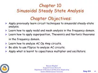
NODAL & MESH ANALYSIS. Circuit Analysis. When a circuit has more than one element, a circuit analysis is required to determine circuit parameters ( v , i , power, etc.) in different parts of the circuit. Circuit Theories: Ohm’s Law Superposition Theorem Kirchhoff’s Voltage and Current Laws

E N D
Circuit Analysis When a circuit has more than one element, a circuit analysis is required to determine circuit parameters (v, i, power, etc.) in different parts of the circuit. • Circuit Theories: • Ohm’s Law • Superposition Theorem • Kirchhoff’s Voltage and Current Laws • Mesh/Nodal Analysis • Source Transformation • Thevenin/Norton Theorem • Wye/Delta Transformation
Mesh (Loop) Analysis • Kirchhoff’s voltage law applies to a closed path in an electric circuit. The close path is referred to as a loop. • A mesh is a simple loop. That is, there are no other loops inside it. • Mesh analysis applies to planar circuits. That is, a circuit that can be drawn on a plane with no crossed wires.
~ I3 I1 I2 Mesh (Loop) Analysis (cont) • Steps: • assume mesh current I1 for Mesh 1, I2 for Mesh 2, etc. • apply KVL for each loop • obtain ‘n’ equations for ‘n’ meshes • i.e., the mesh currents are the unknown variables • solve equations to determine mesh currents • usually done using matrices • obtain currents through each circuit element of interest • apply Ohm’s Law to calculate voltages of interest
Mesh (Loop) Analysis (continued) • Single voltage source • Multiple voltage sources • Voltage and current sources • Supermesh • Dependent sources
Mesh (Loop) Analysis (continued) • Dependent sources: • Current controlled voltage source (CCVS) • Voltage controlled voltage source (VCVS) • Current controlled current source (CCCS) • Voltage controlled voltage source (VCCS)
-j100 W 50 W j5 W -j5 W + + ~ ~ 50/300 V 50/300 V j50 W -j50 W - - Example 1: Find the power dissipated in the 50 resistor using Mesh analysis.
V1 V2 .. .. Vn I1 I2 .. .. In Z11 -Z12 .. .. -Z1n -Z21 Z22 .. .. -Z2n … … .. … .. ... .. .. .. .. -Zn1 -Zn2 .. .. Znn = Mesh Analysis Using Matrix Method [ V ] = [ Z ] [ I ] For a circuit with ‘n’ loops, the matrix equation is: • [ V ] is voltage vector • Vi is the source voltage in Mesh i • Sign convention: +ve voltage if going –ve to +ve (since voltage vector has been moved to the left hand side of the equation) • [ Z ] is impedance matrix (square matrix) • Diagonal element Zii = sum of all impedances in Mesh i • Zik = impedance between Mesh i and Mesh k • [ I ] is the unknown current vector • Ii = current in Mesh i
-j100 W 50 W j5 W -j5 W + + I2 I1 ~ ~ 50/300 V 50/300 V I3 - - j50 W -j50 W Example 1: Mesh (Loop) Analysis (cont)
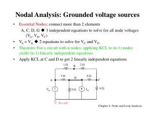
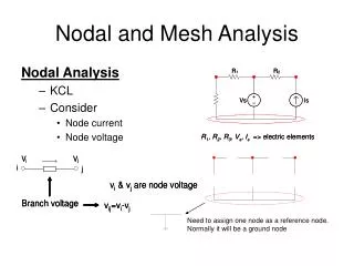
Nodal Analysis • A node is a point in an electric circuit where 2 or more components are connected. (Strictly speaking, it is the whole conductive surface connecting those components.) • Nodal analysis applies to planar and non-planar circuits. • Nodal analysis is used to solve for node voltages. • Sign convention: current leaving node is +ve
V1 V2 ~ ref. node ~ Nodal Analysis (continued) • Steps: • identify all the nodes • select a reference node (usually the node with the most branches connected to it or the ground node of a power source) • assume voltage Vi (w.r.t . reference node) for Node i • assume current direction in each branch • apply KCL at each node • obtain ‘n-1’ equations for ‘n’ nodes (since one node is the reference node) • solve the equations to determine node voltages • apply Ohm’s Law to calculate the currents
Nodal Analysis (continued) • Single current source • Multiple current sources • Voltage and current sources • Supernode • Dependent sources
-j100 W 50 W j5 W -j5 W + + ~ ~ 50/300 V 50/300 V j50 W -j50 W - - Example 1 (revisited): Find the power dissipated in the 50 resistor using Nodal analysis.
-j100 W 50 W j5 W -j5 W + + ~ ~ 50/300 V 50/300 V -j50 W - - j50 W Solving by Nodal Analysis: V3 V1 V2 V4 ref. node KCL at Node 1: get Equation 1 KCL at Node 2: get Equation 2 Why no node equations at Nodes 3 and 4? Solve Equations 1 and 2 to obtain V1 and V2
I1 I2 .. .. In V1 V2 .. .. Vn Y11 -Y12 .. .. -Y1n -Y21 Y22 .. .. -Y2n … … .. … .. ... .. .. .. .. -Yn1 -Yn2 .. .. Ynn = Nodal Analysis Using Matrix Method [ I ] = [ Y ] [ V ] For a circuit with ‘n+1’ nodes, the matrix equation is: [ I ] is the known current vector Ii is the source current in Node i Sign convention: current entering node, +ve (since current vector has been moved to the left hand side of the equation) [ Y ] is admittance matrix (square matrix) Diagonal element Yii = sum of all admittances connected to Node i Yik = admittance between Node i and Node k [ V ] is the unknown voltage vector Vi = voltage at Node i w.r.t. the reference node
Z A A Z ~ V I B B Source Transformation Voltage Source to Current Source Current Source to Voltage Source
Example 1 (revisited): Nodal Analysis and source transformation V1 V2 Current source equivalent for V1 Current source equivalent for V2 Admittances for all other components All admittance values in siemens
V 1 V 2 Example 1 (revisited): Nodal Analysis and source transformation = Similarly, V2 = 55.56/300 Volts V 1 = = 55.56/300 Volts
Zth A A Linear Circuit ~ Eth B B Thevenin’s Theorem Any linear two terminal network with sources can be replaced by an equivalent voltage source in series with an equivalent impedance. • Thevenin Voltage, Eth • voltage measured at the terminals A & B with nothing connected to the external circuit • Thevenin Impedance, Zth • impedance at the terminals A & B with all the sources reduced to zero • i.e. voltage sources short circuited (0 volts) • current sources open circuited (0 amperes)
j5 W -j2 W A 5W 3W 5W + 110/300 V ~ - B Example: Use a Thevenin equivalent circuit at bus “A-B” to calculate the short circuit current at A-B.
Maximum Power Transfer Theorem Maximum power is transferred to a load when the load impedance is equal to the conjugate of the Thevenin Impedance. i.e. ZLoad = Zth*