Download

1 / 38
380 likes | 402 Views
This article explains the concept of ray tracing for lenses and explores the different types of lenses, their functions, and applications. It also covers the thin-lens equation and provides examples of calculations. The article concludes with a discussion on dispersion and the creation of rainbows.

E N D
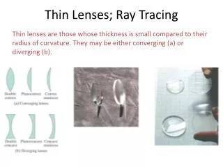
26-6 Ray Tracing for Lenses Lenses are used to focus light and form images. There are a variety of possible types; we will consider only the symmetric ones, the double concave and the double convex.
If we think of a convex lens as consisting of prisms, we can see how light going through it converges at a focal point (assuming the lens is properly shaped).
Ray Tracing for Lenses • The three principal rays for lenses are similar to those for mirrors: • The P ray—or parallel ray—approaches the lens parallel to its axis. • The F ray is drawn toward (concave) or through (convex) the focal point. • The midpoint ray (M ray) goes through the middle of the lens. Assuming the lens is thin enough, it will not be deflected. This is the thin-lens approximation.
26-6 Ray Tracing for Lenses These diagrams show the principal rays for both types of lenses:
26-6 Ray Tracing for Lenses As with mirrors, we use these principal rays to locate the image:
The convex lens forms different image types depending on where the object is located with respect to the focal point:
Applications of Converging Lenses Obviously, converging lenses play an important role in our lives as our eyes are these types of lenses. Often times we need additional corrective lenses to fix our vision. In figure A, we see an eye which converges what we see on the retina. In figure B, we see an eye which converges too LATE. The eye itself is often too short and results in the person being far sighted. In figure C, we see an eye which converges too SOON. The eye itself is often too long and results in the person being near sighted In the later 2 cases, a convex or concave lens is necessary to ensure the image is on the retina.
26-7 The Thin-Lens Equation We derive the thin-lens equation in the same way we did the mirror equation, using these diagrams:
Sample Problem: A converging lens, focal length 20 cm, has a 5-cm high object placed 30 cm from it. a) Draw a ray diagram and construct the image. b) Use the lens equations to calculate i. the position of image ii. the magnification iii. the size of image c) Name the image
Solution b) i. 1/di + 1/do = 1/f 1/di + 1/30 = 1/20 1/di = 1/20 - 1/30 = 3/60 –2/60 = 1/60 di = 60 cm ii. M = - di/do = -60/30 = -2 iii. M = hi/ ho hi = M ho= (-2)5 = -10 cm
Sample Problem: A converging lens, focal length 10 cm, has a 2-cm high object placed 5 cm from it. a) Draw a ray diagram and construct the image. b) Use the lens equations to calculate i. the position of image ii. the magnification iii. the size of image c) Name the image
Solution b) i. 1/di + 1/do = 1/f 1/di + 1/5 = 1/10 1/di = 1/10 - 1/5 = 1/10 –2/10 = -1/10 di = -10 cm ii. M = - di/do = -(-10)/5 = 2 iii. M = hi/ ho hi = M ho= (2)2 = 4 cm
For diverging lenses: • f is negative • do is positive • di is negative • M is positive and < 1 • hi is positive and < ho
Sample Problem: A diverging lens, focal length -15 cm, has a 4-cm high object placed 10 cm from it. a) Draw a ray diagram and construct the image. b) Use the lens equations to calculate i. the position of image ii. the magnification iii. the size of image c) Name the image
Solution b) i. 1/di + 1/do = 1/f 1/di + 1/10 = 1/(-15) 1/di = -1/10 - 1/15 = -3/30 – 2/30 = -5/30 = -1/6 di = -6 cm ii. M = - di/do = -(-6)/10 = 0.6 iii. M = hi/ ho hi = M ho= (0.6)(4) = 2.4 cm
Sample Problem: Two lenses that are 35 cm apart are used to form an image as shown below. Lens 1 is converging and has a focal length f1 = 14 cm; Lens 2 is diverging and has a focal length f2 = -7.0 cm. The object is placed 24 cm to the left of lens 1. a) Use a ray diagram to find the approximate location of the image. b) Is the image upright or inverted? Real or virtual? Explain.
26-8 Dispersion and the Rainbow The index of refraction varies slightly with the frequency of light; in general, the higher the frequency, the higher the index of refraction. This means that refracted light is “spread out” in a rainbow of colors; this phenomenon is known as dispersion.
26-8 Dispersion and the Rainbow Rainbows are created by the dispersion of light as it refracts in a rain drop.
26-8 Dispersion and the Rainbow As the drop falls, all the colors of the rainbow arrive at the eye.
26-8 Dispersion and the Rainbow Sometimes a faint secondary arc can be seen.
Summary of Chapter 26 • A wave front is a surface along which the wave phase is constant. Rays, perpendicular to the wave fronts, indicate the direction of propagation. • The angle of incidence equals the angle of reflection. • The image formed by a plane mirror is upright, but appears reversed left to right; appears to be the same distance behind the mirror as the object is in front of it; and is the same size as the object.
Summary of Chapter 26 • Spherical mirrors have spherical reflecting surfaces. A concave mirror is curved inward, and a convex one outward. • Focal length of a convex mirror: • Focal length of a concave mirror: • An image is real if light passes through it, virtual if it does not. • Mirror equation:
Summary of Chapter 26 • Magnification: • Refraction is the change in direction of light due to a change in speed. • The index of refraction gives the speed of light in a medium:
Summary of Chapter 26 • Snell’s law: • Light entering a medium of higher n is bent towards the normal; light entering a medium of lower n is bent away from the normal. • When light enters a medium of lower n, there is a critical angle beyond which the light will be totally reflected.
Summary of Chapter 26 • At Brewster’s angle, the reflected light is totally polarized: • A lens uses refraction to bend light and form images. • Thin-lens equation:
Summary of Chapter 26 • Magnification: • The index of refraction varies with frequency; different frequencies of light are bent different amounts. This is called dispersion.