Download
1 / 37
370 likes | 406 Views
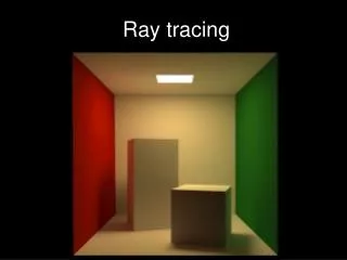
Ray Tracing. Writing a Very Simple Version. What Makes a Good Picture?. Contents (3D models). Lighting. Reflection. Shadow. Surface textures. Synthetic Camera Model. projector. p. image plane. projection of p. center of projection. Method A: Object Order Algorithm

E N D
Ray Tracing Writing a Very Simple Version
What Makes a Good Picture? • Contents (3D models). • Lighting. • Reflection. • Shadow. • Surface textures.
Synthetic Camera Model projector p image plane projection of p center of projection
Method A: Object Order Algorithm (Process one polygon at a time.)
3D to 2D Projection • OK, so we can map a 3D point (or vertex) to 2D image. • But what about a 3D surface? • Polygons are made from points. • Actually, we only need triangles!
Scan Conversion • Also called rasterization. • The 3D to 2D Projection gives us 2D vertices (points). • We need to fill in the interior.
Method B: Screen Order Algorithm (Process one pixel at a time.)
Ray Tracing Algorithm • An overview in Pharr’s 1.2 • More detail in Watt’s 10.3.1 (pp.284-286) and 12.2-12.4 (pp.342-354) Transmitted Reflected
Creating a Ray • Parameters: • Image Plane (position, size, and resolution) • Viewpoint • Which ray (x, y)?
Define the Projection Plane • Given: • Viewpoint (or eye position, camera position): E • Viewing direction: D • Upward direction (usually the sky): U • Find the 4 corners of the projection screen • First, find the center of the screen (E + D * d) • You may define your own distance (d) • The X/Y directions of the screen may be obtained by: • X = D x U and Y = D x X • Extend to the corners • Then divide the screen into pixels. • Q: Use the pixel center or corner?
Ray-Object Intersection • For example: sphere (x-x0)2+(y-y0)2+(z-z0)2=r2 • Ray: (x,y,z)=(x1,y1,z1)+t(xd,yd,zd) • Find t that satisfy (x-x0)2+(y-y0)2+(z-z0)2=r2 • What does it mean if t < 0? • Normal vector? • Also easy for planes, cones, …etc.
Ray-Object Intersection • Plane: (x,y,z)= V0 + s1*(V1 -V0 )+ s2*(V2 -V0 ) • Ray: (x,y,z)= (x1,y1,z1) + t (xd,yd,zd) • Find s1, s2 , t that produce the same (x,y,z) • Intersection found if 0 s1, s2 1 and t > 0 V2 V1 V0
Ray-Triangle Intersection • Intersection found if: t > 0 and s1+s2 1 • Now you can handle 3D OBJ models!! V2 V0 V1
Möller–Trumbore Algorithm • A fast method for calculating the intersection of a ray and a triangle in 3D. • See: Fast, Minimum Storage Ray/Triangle Intersection, Möller & Trumbore. Journal of Graphics Tools, 1997.
Shading Models • Pixel color = ambient + diffuse + specular + reflected + transmitted • The weight of each is determined by the surface properties. • We will discuss each of them within the next a few lectures.
Lighting (Shading) & Shadow • Point light is easy to implement. • How to determine a surface point is in the shadow? Use a shadow ray (from intersection point to light). • Shading will be introduced in the next lecture.
Reflection and Refraction • Reflected ray is determined by: • incoming ray and normal vector. • Refracted ray is determined by: • Incoming ray • Normal vector • And density • Snell’s law: • I sin i = t sin t i t
Recursive Algorithm • The reflected ray, refracted ray, and shadow ray are traced recursively. • Termination condition: • Depth of trace • Weight (to the final pixel color) of ray
Advantage • We get all the following automatically: • Hidden surface removal • Shadow • Reflection • Transparency and refraction
Disadvantage • Slow. Many rays are spawned. • Slow. Ray-object intersection for every ray and every object. (We will discuss how to avoid this in the next lecture). • The lighting is still not completely right!
Assignments 1 & 2 – A Ray Tracer • Split into two parts. • Part A due in 2 weeks. • Camera module • Object module • No recursive ray tracing • Simple output (just black and white) • The rest (Part B) are due in 2 more weeks.
Required Modules • Ray Generation Module • Ray Object Intersection Module • Shading Module (Recursive Rays Gen.) • Display (Output) Module
Ray Generation Module • Reads camera setup from input files. • Definition of eye position and image plane in 3D coordinates. • Generates a ray if given image screen coordinates (x, y) • Note that x and y may be real numbers (not integers).
Intersection Module • Sphere and triangle types only (for now). • Ray-object intersection. • Light (for Part B).
Shading Module • Integration of other modules. • Shading (for Part B). • Spawn reflected and refracted rays.
Part A • Ray generation module • Ray-object intersection module • Spheres and triangles only • Shading module: • No shading. No reflection and refraction. • Display module (black & white only)
Ray-Object Intersection • For example: sphere (x-x0)2+(y-y0)2+(z-z0)2=r2 • Ray: (x,y,z)=(x1,y1,z1)+t(xd,yd,zd) • Find t that satisfy (x-x0)2+(y-y0)2+(z-z0)2=r2
HW2 (Part B) • Objects materials • Color and reflections • Checkerboard. • Shading module: • Add shading, reflection, and refraction. • Display module: • PPM library will be provided. • Add a demo scene of your own.
Lighting (Shading) & Shadow • Point light is easy to implement. • How to determine a surface point is in the shadow? Use a shadow ray (from intersection point to light). • Shading will be introduced in the next lecture.
Reflection and Refraction • Reflected ray is determined by: • incoming ray and normal vector. • Refracted ray is determined by: • Incoming ray • Normal vector • And density • Snell’s law: • I sin i = t sin t i t
Output to PPM Format • A image forma that is easy to support • IO code available as ImageIO.[c,h] • Download IrfanView (freeware) to view the generated output images.
Usage of ImageIO.c int main(int argc, char* argv[]) { ColorImage image; int x, y; Pixel p={0,0,0}; initColorImage(256, 256, &image); for (y=0; y<256; y++) { for (x=0; x<256; x++) { p.R = y; writePixel(x, y, p, &image); } } outputPPM("reds.ppm", &image); }