Download
1 / 43
440 likes | 546 Views
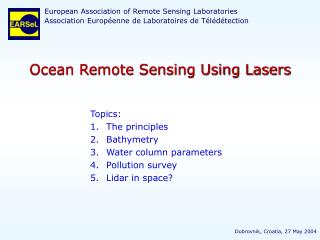
European Association of Remote Sensing Laboratories Association Européenne de Laboratoires de Télédétection. Ocean Remote Sensing Using Lasers. Topics: The principles Bathymetry Water column parameters Pollution survey Lidar in space?. Dubrovnik, Croatia, 27 May 2004. 1. The principles.

E N D
European Association of Remote Sensing Laboratories Association Européenne de Laboratoires de Télédétection Ocean Remote Sensing Using Lasers • Topics: • The principles • Bathymetry • Water column parameters • Pollution survey • Lidar in space? Dubrovnik, Croatia, 27 May 2004
1. The principles wavelength wave-number spectralrange photonenergy frequency The electromagnetic spectrum rays x rays UV LightdetectionandrangingLidar VIS IR water is transparent org. matter is absorbing micro-waves RadiodetectionandrangingRadar Radar FM AM radio waves
1. The principles Oceanic Lidar • Light sources with short pulses nanosecond pulse lasers Lidar in the atmosphere • Time-resolved signal detection GHz bandwidth detectors • Range resolution z fromwith c speed of light What can be measured? • Water depthfrom seabottom reflection • substances at the water surface and underwaterfrom backscatterand fluorescence Australian Antarctic Divisionhttp://www.antdiv.gov.au
1. The principles Oceanic Lidar • Lidar equation for receiver power P(z): opt. filter detector telescope laser flight altitude H • A homogeneous water column:c=const., =const. z = 0 water: substances: m: refractive index concentration n c=cex+cemattenuation coeff. efficiency water depth z seafloor
2. Bathymetry: water depth sounding Motivation: • Nautical charts are often based on very old data • Until 1997:almost no acoustic data used • Since 2002:approx. 2500 Gbyte/year of acoustic imagery data • Nearshore charting with lidar has become fast and reliable Optech Inc., Canada Scanning with laser pulses andregistration of induced signals
2. Bathymetry: water depth sounding Method: Signal echo versus time-of-flightof elastic backscattered light sea surface:IR laser pulse(=1064 nm) seafloor: green laser pulse (= 532 nm) Optech Inc., Canada Scanning with laser pulses andregistration of induced signals
2. Bathymetry: water depth sounding G. Guenther et al., 2000 • Signal response function: • Surface return • Bottom return • Signals from the water column Optech Inc., Canada Scanning with laser pulses andregistration of induced signals
2. Bathymetry: water depth sounding Chart based on 5 overlapping flight tracks G. Guenther et al., 2000
2. Bathymetry: water depth sounding Solander Island, New Zealand Optech Inc., Canada Surveying underwater pinnacles
2. Bathymetry: water depth sounding sunken cargo vessel3 m below sea surface Baltic Sea,water depth 25 m Swedish Maritime Administration
2. Bathymetry: water depth sounding Looe Key, Florida Channel through a coral reef Optech Inc., Canada
2. Bathymetry: water depth sounding digital underwater elevation model Looe Key, Florida Channel through a coral reef Optech Inc., Canada
2. Bathymetry: water depth sounding Maximum depth 60 m Bathymetric Lidar Performance Example: Shoals 1000 Vertical accuracy ± 0.15 m Horizontal accuracy ±3 m (DGPS) Pixel distance 8 m Operating altitude 400 m Scan swath width 220 m Operating speed 70 m/s Vertical accuracy ± 0.25 m Int. Hydrographic Associationrequirements for nautical charting Small object detection 111 m3 Small object detection/identification Challenges Seafloor classification (sand, mud, gravel, stones, vegetation) • Further reading: • http://www.optech.on.ca • G. Guenther et al., EARSeL eProceedings 1, 2001http://las.physik.uni-oldenburg.de/eProceedings/vol01_1/01_1_guenther1.pdf Land-water discrimination Near-shore applicability (waves, foam) Safe navigation (shoreline, anchorage, wrecks)
3. Water column parameters Method: Signal echo versus time-of-flightat higher wavelengths 1.00 ex= 270 nm 0.50 H2O Raman scattering depth profiles of substances 0.20 • fluorescence fluorescence, typically of North Sea water 0.10 pure water absorption coefficient /m-1 proteins Gelbstoffeplankton pigments 0.05 proteins Gelbstoffe • Raman scattering 0.02 Chlorophyll attenuation 0.01 300 400 500 600 700 wavelength /nm
3. Water column parameters Fluorescence spectra do not depend on excitation wavelength! Fluorescence of molecules fluorescence absorption relaxation phosphorescence intersystem crossing absorption relaxation singlet state S1 singlet state S1 triplet state T1 energy energy : 1 ns ... 10 µs > 1 ms singlet state So singlet state So distance of nuclei distance of nuclei
3. Water column parameters Raman spectra preserve the vibrational energy E! Molecular scattering Stokes shift anti-Stokes shift elastic Rayleigh scattering Raman scattering Raman scattering
3. Water column parameters Water Raman scattering: O O O H H H H H H free molecules: liquid water: arb. intensity arb. intensity 3000 3400 3800 /nm From: Schröder M et al., Applied Optics 42(21), 4244-4260, 2003
3. Water column parameters The lidar equation • water Raman scattering • fluorescence • fluorescence normalised to Raman scattering
3. Water column parameters Onboard ship R/V Polarstern From: Ohm K et al., EARSeL Yearbook 1997. Paris, 1998
3. Water column parameters Onboard ship Chlorophyll vs. depthin the Antarctic Ocean 1.00 ex= 270 nm 0.50 H2O Raman scattering 0.2 pure water absorption coefficient /m-1 fluorescence, typically of North Sea water 0.10 0.05 proteins Gelbstoffe 0.02 Chlorophyll 0.01 300 400 500 600 700 wavelength /nm From: Ohm K et al., EARSeL Yearbook 1997. Paris, 1998 arb. units
3. Water column parameters Onboard ship Underway measurements Depth Profiling Fluorescence Lidar Performance: Maximum depth Chlorophyll 20 m Gelbstoffe 40 m Water Raman 40 m Elastic backscatter 60 m Vertical accuracy ± 0.15 m Maximum depth: Challenges: Open ocean 100 m Coastal waters 10..20 m Temperature, salinity Underwater imaging Lidar signal deconvolution
3. Water column parameters Lidar signal deconvolution Measured signal: instrument response function where: ideal signal measured signal ideal signal signal with 0.1% noise, Richardson-Lucy algorithm signal with 0.1% noise, Fourier Transformation From: Harsdorf & Reuter, EARSeL eProceedings 1, 2001
3. Water column parameters Airborne 1983 • depth profilingat nighttime • depth integratingin daylight
3. Water column parameters Airborne Tidal fronts UV attenuationex 308 - em 344 VIS attenuationex 450 - em 533 gelbstoff flu.ex 308 - em 366 chlorophyll flu.ex 450 - em 685 From: Reuter R et al., Int J Remote Sensing, 14: 823-848, 1993
3. Water column parameters Airborne Tidal fronts gelbstoff fluorescenceex 308 – em 360 From: Reuter R et al., Int J Remote Sensing, 14: 823-848, 1993
3. Water column parameters Canary Islands: wind-induced upwelling trade winds blue:Gelbstoffe bleached by UV red:Gelbstoffe broughtto the sea surface by upwelling From: Milchers et al., 3rd Workshop Lidar Remote Sensing of Land and Sea, EARSeL, 1997
4. Pollution monitoring to do:
4. Pollution monitoring Methods: 1.00 ex= 270 nm 1. signal loss of water Raman scatter 0.50 H2O Raman scattering 0.2 fluorescence, typically of North Sea water 0.10 pure water absorption coefficient /m-1 0.05 proteins Gelbstoffe 0.02 Chlorophyll 0.01 300 400 500 600 700 wavelength /nm
4. Pollution monitoring Methods: Intensity 1. signal loss of water Raman scatter 2. the fluorescence signature 300 350 400 450 500 550 600 650 700 wavelength /nm crude oils refined oils Diesel 250 Agrill 600 Auk Gasoline 500 200 Brent Reformat 400 150 Intensity Intensity 300 100 200 50 100 0 0 300 400 500 600 700 300 400 500 600 700 wavelength /nm wavelength /nm From: Hengstermann T & R Reuter, EARSeL Adv Rem Sens, 1, 52-60, 1992
4. Pollution monitoring Airborne maritime surveillance approx. 30 litres very light crude
3+4. Airborne Depth resolving 40 m Nighttime only Fluorescence Lidar Performance Maximum depth 20 m Integrating upper 2-10 m Parameters chlorophyll 0.1-100 µg/l Gelbstoffe coastal conc. mineral particles 0.1-10 mg/l attenuation coeff. c < 10 m-1 oil film thickness 0.1-10 µm oil type 5...10 classes certain chemicals Reliable, compact, transportable Challenges Affordable Data fusion with other sensor data
5. Lidar in space? Rationale: • Measures Gelbstoff in the open ocean • No ambiguity in coastal waters • Verifies oil spillsin SAR images Possibly an add-onto atmospheric lidars
5. Lidar in space? Atmospheric lidars: LITE http://www-lite.larc.nasa.gov/ http://www-lite.larc.nasa.gov/
5. Lidar in space? Atmospheric lidars: LITE http://www-lite.larc.nasa.gov/ Flight from the Atlantic (left) over the Sahara (centre, right)
5. Lidar in space? Atmospheric lidars: WALES (Water vApour Lidar Experiment in Space)ESA Living Planet Programme, 2008-2010 http://www.esa.int/esaLP/ASE77YNW9SC_wales_0.html
5. Lidar in space? Radiative transfer simulation From: Bartsch B et al, Applied Optics, 32, 6732-6741, 1993
5. Lidar in space? Radiative transfer simulation From: Bartsch B et al, Applied Optics, 32, 6732-6741, 1993
5. Lidar in space? Radiative transfer simulation From: Bartsch B et al, Applied Optics, 32, 6732-6741, 1993
5. Lidar in space? Radiative transfer simulation From: Bartsch B et al, Applied Optics, 32, 6732-6741, 1993
5. Lidar in space? Radiative transfer simulation From: Bartsch B et al, Applied Optics, 32, 6732-6741, 1993
Further reading: • Measures RM: Laser remote sensing.John Wiley & Sons, New York (1984) • Kirk JTO: Light and photosynthesis in aquatic ecosystems.Cambridge University Press, 2nd ed. (1994) • Mobley CD: Light and water.Academic Press (1994) • Ishimaru A: Wave propagation and scattering in random media.Vol. 1 +2. Academic Press (1978) • Andrews LC & RL Phillips: Laser beam propagation throughrandom media. SPIE (1998) • Various papers from many lidar research groups in EARSeL eProceedingshttp://las.physik.uni-oldenburg.de/eProceedings/