Download
1 / 12
120 likes | 236 Views
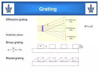
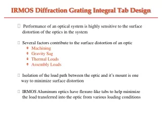
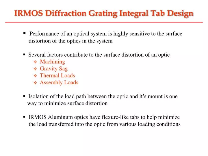
IRMOS Diffraction Grating Integral Tab Design. Performance of an optical system is highly sensitive to the surface distortion of the optics in the system Several factors contribute to the surface distortion of an optic Machining Gravity Sag Thermal Loads Assembly Loads

E N D
IRMOS Diffraction Grating Integral Tab Design • Performance of an optical system is highly sensitive to the surface • distortion of the optics in the system • Several factors contribute to the surface distortion of an optic • Machining • Gravity Sag • Thermal Loads • Assembly Loads • Isolation of the load path between the optic and it’s mount is one • way to minimize surface distortion • IRMOS Aluminum optics have flexure-like tabs to help minimize the load transferred into the optic from various loading conditions
IRMOS System level FEM (Dewar and Adapter removed) IRMOS System level FEM
Integral Mounting Tab IRMOS Diffraction Grating
Diffraction Grating Assembly Loads • Tab flexures must be designed such that they are flexible enough to allow motion of the tab without violating optical surface RMS requirements, but strong enough to take the stresses induced by the motions of the tabs • One concern with the integral tab design is that the flexibility of the tabs allows for minimal translations and rotations during assembly • In high precision optics these minimal motions can induce undesirable distortion in the optical surface • IRMOS project set requirements for the minimum motion of a tab in any one direction during assembly • Translation : 0.005” • Rotation : 0.1 deg • These motions could arise if the tabs had to be moved to align bolt holes between the grating and it’s carrier, or if shims were required under the grating tabs during alignment of the optics
Diffraction Grating FEA • Grating FEM uses a combination of solid and plate elements • RSSCON cards used to connect shell and solid elements • Solid element face equal to shell element thickness • Shell edge is placed in the middle of the solid face • 3 bolt holes in the mounting tabs were used as the boundary conditions • Load cases – gravity, thermal, assembly • Using FEA, Optical surface distortion can be obtained for all load cases and compared to the requirements set by optics group • Iterative process If requirements are not met for a specific load case, FEM is modified and analysis is redone • Results of the FEA produce an optimum flexure design that can meet the stiffness requirements of gravity, thermal, and assembly loads and also be flexible enough to not transmit the motion to the surface of the optic
FEA Grating Optical Distortion Results Assembly Loads (.044 micron RMS requirement) ** rz limited by Fty = 22500 psi Gravity Loads (.032 micron RMS requirement) Thermal Loads (.032 micron RMS requirement) * Grating is limited to a .1 degree gradient in the z-direction based on the .032 micron RMS requirement
FEA Grating Optical Distortion Results Stresses in the grating tab flexures due to a .005” Dy motion of the –y tab (Fty = 22500 psi)
FEA Correlation • IRMOS diffraction grating test optics were used as one method of FEM validation • Test optics were attached to a “dummy” optical bench by the 3 integral mounting tabs • Test loading conditions included various torque sequences and various shim thickness/ placement as defined by FEA • Testing was performed at room temperature, with the grating oriented such that gravity was applied along the y-axis • Optical surface distortion was measured using an interferometer y x Test Grating Dummy Bench
FEA /Optical Test Results • Results from FEA and optical testing compared RMS Surface Error Induced by DZ Assembly Load (.005” shim placed under –y tab) ** RMS surface error of unmounted grating was determined to be . 136 waves, this was removed from the optical test data • Good correlation between analysis and test results seen for all other load cases
Summary • FEA was used as an efficient and effective tool for optimizing the design of the diffraction grating tab flexure for maximum flexibility and minimum stress • Interferometric testing of the grating optical surface distortion was used to correlate FEA results with optical test results, and provided FEM validation • FEA methods used in the grating tab flexure design optimization were able to be applied to the flexible mounting tabs in all of the Aluminum IRMOS optics