Download
1 / 14
140 likes | 212 Views
Integral Hub NSTX Design. P. Heitzenroeder B. Paul P. Titus. Features of design: Welded extensions to TF conductors provides joint-free regions for current streamlines to transition from vertical to horizontal. Original B*R is 0.51; field at TF joint is 5.2 T at r=0.098 m.

E N D
Integral Hub NSTX Design P. Heitzenroeder B. Paul P. Titus
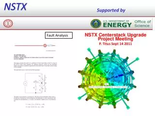
Features of design: • Welded extensions to TF conductors provides joint-free regions for current streamlines to transition from vertical to horizontal. • Original B*R is 0.51; field at TF joint is 5.2T at r=0.098 m. • Upgrade B*R=0.934 • This design moves bolted joint interface from 4.7 T region (r=0.2 m) at TF sfc. to 3.3 T (r=.28m.) region on bottom, and to 2.22 (r=.42m) at top. (37 and 58% reduction in fields at joints) • Increases contact areas for joints to 17.3 top and 11 sq. in. bottom. (J=7.5 and 11.8 kA/in2). • Provides bonded integral hubs for positive torque restraint & lower shear stress in GlEp. The integral hub center stack assembly G10 torque reaction discs keyed directly into turns OH preload mechanism Turns bonded to create integral hubs OH coil wound in place OH support
Updates to Pete’s analyses • Four Updates to Match Charlies’ Gfun Heat-up • Correct Turn Multiplier • Correct Thermal Conduction of Air • Correct Inner Leg Conduction Cross Section by use of a Fictitious Packing Fraction • 6.5 Seconds Flattop
Coupled Electromagnic-Thermal Analysis Then a Stress Pass with an LDREAD of Lorentz Forces and Temperatures
Integral Hub Details • G10 plate connection keyed into turns for OOP restraint. • Wedge-shaped turns bonded together into integral hubs. • OH coil wound on TF • Preload mechanism similar to present design. • Flex links (similar to present design) to accommodate axial thermal expansion of center stack.
TF conductor • Has e-beam or friction stir welded extensions at connection regions. • Moves bolted electrical joints radially out to lower field regions. • Greatly increases bolted electrical joint area. • Provides joint-free regions for current to change direction. • Conductors bonded together to form integral hubs for good OOP support. • Asymmetric – bottom sized to pass thru center tube; top sized for maintenance access. Also, top could be made the same as the bottom if desired. 2.88 1.84 Lower extension Upper extension welds
Configuration provides good OOP load reaction • Torque reaction disc • Diaphragm action permits axial thermal expansion of center column. • Spun dimple may not be needed based on P. Titus’ analysis. TF outer legs Existing umbrella structure
The bottom uses conservatively designed bolted extensions • 6 x 1.8” contact area & 3-3/4” tension bolts. • G-10 discs top (not shown) & bottom keyed directly into welded extensions and restrained by torque disc provides OOP support. Flex straps