Download
1 / 68
710 likes | 727 Views
CHAPTER 3: FORMING PROCESS 3.1 INTRODUCTION 3.2 BULK DEFORMATION PROCESSES 3.2.1 Rolling Process 3.2.2 Forging Process 3.2.3 Extrusion Process 3.2.4 Wire and Bar Drawing 3.3 SHEET-METAL FORMING PROCESSES 3.3.1 Cutting Operations

E N D
CHAPTER 3:FORMING PROCESS 3.1 INTRODUCTION 3.2 BULK DEFORMATION PROCESSES 3.2.1 Rolling Process 3.2.2 Forging Process 3.2.3 Extrusion Process 3.2.4 Wire and Bar Drawing 3.3 SHEET-METAL FORMING PROCESSES 3.3.1 Cutting Operations 3.3.2 Bending Operations 3.3.3 Drawing Operations 3.3.4 Die and Presses
3.1 Introduction • Metal forming processes can be classified into two basic categories: (1) bulk deformation processes (2) sheet metalworking processes. Figure 3.1: Classification of metal forming operations
Bulk deformation processes are generally characterized by significant deformations and massive shape changes, and the surface area-to-volume of the work is relatively small. Figure 3.2: Basic bulk deformation processes: (a) Rolling, (b) forging, (c) Extrusion, (d) Drawing
Sheet Metalworking processes are forming and related operations performed on metal sheets, strips, and coils. The surface are-to-volume ration of the starting metal is high. Figure 3.3: Basic sheet metal working processes: (a) Bending, (b) Drawing, (c) Shearing
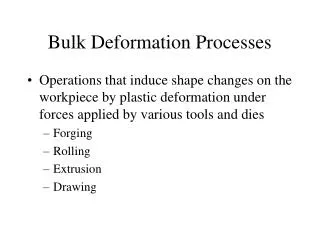
3.2 Bulk Deformation Processes • Deformation processes work by stressing the metal sufficiently to cause it to plastically flow into the desired shape. • Bulk deformation processes are performed as cold, warm, and hotworking operations. • Cold and worm working is appropriate when the shape change is less severe, and there is a need to improve mechanical properties and achieve good finish on the part. • Hot working is generally required when massive deformation of large workparts is involved. 3.2.1 Rolling Process • Process of reducing the thickness (or changing the cross-section) of a long workpiece by compressive forces applied through a set of rolls (Figure 3.4). • Plates, which are generally regarded as having a thickness greater than 6 mm, are used for structural applications, such as machine structures, ship hulls, boilers, bridges, and nuclear vessel. • Plates can be as much as 0.3 m thick for the support for large boilers, 150 mm thick for reactor vessels, and 100–125 mm thick for battleships and tanks.
Figure 3.4: Schematic outline of various flat and shape rolling processes
Sheets are generally less than 6 mm thick; they are provided to manufacturing facilities as flat pieces or strip in coils for further processing into various products. • They are used for automobile and aircraft bodies, appliances, food and beverages containers, and kitchen and office equipment. • This chapter describes the basic process of flat rolling and shape rolling operations. 3.2.1.1 Flat Rolling and Its Analysis • In flat rolling, the work is squeezed between two rolls so that its thickness is reduced by an amount called the draft: d = ho – hf 3.1 • The true strain experienced by the work in rolling is based on before and after stock thicknesses. In equation form, є = In (ho/ hf) 3.2 • The true strain can be used to determine the average flow stress Yavg applied to the work material in flat rolling that is defined: Yavg = Kєn/(1+ n) 3.3
A schematic illustration of the flat rolling process is shown in Figure 3.5. Figure 3.5: (a) Schematic illustration of the flat rolling process, (b) Friction forces acting on strip surfaces, (c) The roll force, F, and the torque acting on the rolls • Maximum possible draft that can be accomplished with a given coefficient of friction, given by: dmax = µ2R3.4
Roll force, F, is needed because the rolls apply the pressure on the material in order to reduce its thickness (Figure 3.5c). This is, F = YavgwL 3.5 • Contact length can be approximated by: L = √R (ho – hf) 3.6 • Torque for each roll is: T = 0.5FL 3.7 • The power required per roll can be estimated from the formula P = 2NFL 3.8 Example Calculation of Flat Rolling • Determine if the friction is sufficient to permit the rolling operation to be accomplished. If so, calculate the roll force, torque, and power. Data given by: w = 300 mm, ho = 25 mm, R = 250 mm, hf = 22 mm, N = 50 rev/min, K = 275 MPa, n = 0.15, and µ = 0.12.
Solution • The draft attempted in this rolling operation is d = 25 – 22 = 3 mm • Maximum possible draft for the given coefficient of friction is dmax = (0.12)2(250) = 3.6 mm • To compute rolling force, we need the contact length and the average flow stress. L = √250(25 – 22) = 27.4 mm • The average flow stress is determined from the true strain: є = In (25/22) = 0.128 Yavg = 275(0.128)0.15/(1+ 0.15) = 175.7 MPa • Rolling force is determined from, F = 175.7(300)(27.4) = 1,444,786 N • Torque required to drive each roll is given by, T = 0.5(1,444,786)(27.4 x 10⁻³) = 19,786 Nm • Power is obtained from, P = 2(50)(1,444,786)(27.4 x 10⁻³) = 207,201 Nm/s @ W
3.2.1.2 Shape Rolling • Products made by shape rolling include construction shapes such as I-beams, L-beams, and U-channels, rails for railroad tracks, and round and square bars and rods (see Figure 3.6). • The process is accomplished by passing the work through rolls that have the reverse of the desired shape. • Other deformation process related to shape rolling such as ring rolling, thread rolling, gear rolling, and roll piercing. Figure 3.6: Some of the steel product made in a shape rolling
3.2.1.3 Rolling Mills • The basic rolling mill consists of two opposing rolls and is referred to as a two-high. The two-high configuration can be either reversing or nonreversing. • The width of rolled products may range up to 5 m and be as thin as 0.0025 mm. • Rolling speeds may range up to 25 m/s for cold rolling, or even higher in highly automated and computer controlled facilities. Figure 3.7: Various configuration of rolling mills: (a) 2-high, (b) 3-high, (c) 4-high, (d) cluster mill, and (e) tandem rolling mill
3.2.2 Forging Process • Forging is a deformation process in which the work is compressed between two dies, using either impact load (forging hammer machine)or gradual pressure (forging press machine) to form the part. • Press machine are preferred for use with aluminum, magnesium, bronze, brass and hammer machine are usually preferred for use with steels, titanium, copper, refractory-metal alloys. • Forging operations produce discrete parts such as bolts and rivets, connecting rods, engine crankshaft, and gears. • Metal flow and grain structure can be controlled, so forged parts have good strength and toughness: they can be used reliably for highly stressed and critical applications. • Forging may be done at room temperature (cold forging) or at elevated temperatures (hot forging), depending on the temperature. • Forging generally require additional finishing operations, such as heat treating, to modify properties, and then machining to obtain accurate finished dimensions.
3.2.2.1 Open-Die Forging and Its Analysis • The work is compressed between two flat dies and reduces the height of the work and increase its diameter. • This forging operation, known as upsetting or upset forging. Figure 3.8: Open-die forging operation • The true strain experienced by the work during the process can be determined by є = In (ho/ h) 3.9 • Estimates of force to perform upsetting can be calculated by F = YfA3.10
The factors can be cause the actual upsetting force to be greater than what is predicted by Equation 3.10. • As an approximation, we can apply a shape factor to Equation 3.10 to account for effects of the D/h ratio and friction. F = KfYfA 3.11 • Kf is the forging shape factor, defined as Kf = 1 + [(0.4µD)/h] 3.12 Figure 3.9: Actual deformation of workpart in open-die forging: (1) Start of process, (2) partial deformation, and (3) final shape
Example Calculation of Open-Die Forging • A cylindrical workpiece is subjected to a cold upset forging operation. The starting piece is 75 mm in height and 50 mm in diameter. It is reduced in the operation to a height of 36 mm. the work material has a flow curve defined by K = 350 MPa and n = 0.17. Assume a coefficient of friction of 0.1. Determine the force as the process begins, at intermediate heights of 62 mm, 49 mm, and at the final height of 36 mm. Solution • Workpiece volume V = 75(502/4) = 147,262 mm3. At the moment contact is made by the upper die, h = 75 mm and the force F = 0. At the start of yielding, h is slightly less than 75 mm, and we assume that strain = 0.002, at which the flow stress is Yf = Kєn = 350(0.002)0.17 = 121.7 MPa • The diameter is still approximately D = 50 mm and area A = (502/4) = 1963.5 mm2. For these conditions, the adjustment factor Kfis computed as Kf = 1 + [(0.4)(0.1)(50)/75] = 1.027 • The forging force is F = 1.027(121.7)(1963.5) = 245,410 MPa
At h = 62 mm, є = In (75/ 62) = 0.1904 Yf = 350(0.1904)0.17 = 264.0 MPa • Assuming constant volume, and neglecting barreling, A = 147,262/62 = 2375.2 mm2and D = 55 mm Kf = 1 + [(0.4)(0.1)(55)/62] = 1.035 F = 1.035(264)(2375.2) = 649,303 N • Similarly, at h = 49 mm, F = 955,642 N, and at h = 36 mm, F = 1,467,422 N.
3.2.2.2 Impression-Die Forging • Sometimes called closed-die forging, is performed with dies that contain the inverse of the desired shape of the part. • As the die closes to its final position, flash is formed by metal in which this flash must be cut away from the part. • The force formula is the same as Equation 3.11, but its interpretation is slightly different; F = KfYfA 3.13 In hot forging, the appropriate value of Yf is the yield strength of the metal at the elevated temperature. Figure 3.10: Impression-die forging operation
3.2.2.2.1 Forging-Die Design • The design of forging dies requires a knowledge of the strength and ductility of the workpiece material, its sensitivity to deformation rate and temperature, its frictional characteristics, and the shape and complexity of the workpiece. • Indicate the forging dies terminology and guidelines used in the design of forgings and forging dies. ~ The parting line is the plane that divides the upper die from the lower die. ~ Draft is the amount of taper on the sides of the part required to remove it from the die. Typical draft angles are 3° on aluminum and magnesium parts and 5° to 7° on steel parts. Draft angles on precision forgings are near zero. ~ A web is thin portion of the forging that is parallel to the parting line, while the rib is a thin portion that is perpendicular to the parting line. ~ Fillet and corner radii. Small radii tend to limit metal flow and increase stresses on die surfaces during forging.
~ Flash formation plays a critical role in impression-die forging by causing pressure buildup inside the die to promote filling of the cavity. The gutter permits excess metal to escape without causing the forging load to reach extreme values. Figure 3.11: Terminology for a conventional impression-die in forging
3.2.2.3 Flashless Forging • The term flashless forging in which the raw workpiece is completely contained within the die cavity during compression, and no flash is formed. • Most important is that the work volume must equal the space in the die cavity within a very close tolerance. • Flashless forging is often classified as a precision forging process. • Coining is a special application of flashless forging in which fine details in the die are impressed into the top and bottom surfaces of the workpart. Figure 3.12: Coining operation: (1) Start of cycle, (2) Compression stroke, (3) ejection of finished part
3.2.3 Extrusion Process • Extrusion is a compression process in which the work metal is forced to flow through a die opening to produce a desired cross-sectional shape. • Extrusion operations produce continuous parts such as railing for sliding doors, tubing having various cross-sections, door, and window frames. • Extruded products can be cut into desired lengths, which then become discrete parts such as brackets, gears, and coat hangers. • Commonly extruded materials are aluminum, copper, steel, magnesium, and lead. 3.2.3.1 Types of Extrusion • Classifying the operations is by physical configuration, in which the two principal types are direct and indirect extrusion. • Direct extrusion also called forward extrusion is illustrated in Figure 3.13.
A metal billet is loaded into a container, and a ram compresses the material, forcing it to flow through one or more openings in a die at the opposite and of the container. Figure 3.13: Direct extrusion Figure 3.14: (a) Direct extrusion to produce a hollow or semi-hollow cross section, (b) Hollow and (c) semi-hollow cross section
Indirect extrusion also called backward extrusion or reverse extrusion, the die is mounted to the ram rather than at the opposite end of the container. • Indirect extrusion can produce hollow cross section, the ram is pressed into the billet, forcing the material to flow around the ram and take a cup shape. Figure 3.15: Indirect extrusion to produce (a) A solid cross section, (b) a hollow cross section
Another classification is by working temperature; cold, warm, or hot extrusion. • Hot extrusion involves prior heating of the billet to a temperature above its re-crystallization temperature. • This reduces strength and increases ductility of the metal, permitting more extreme size reductions and more complex shapes to be achieved in the process. • Additional advantages include reduction of ram force, increased ram speed, and reduction of grain flow characteristics in the final product. • Glass is sometimes used as a lubricant in hot extrusion; in addition to reducing friction. • Cold extrusion and warm extrusion are generally used to produce discrete parts, often in finished form. • Advantages of cold extrusion include increase strength due to strain hardening, close tolerances, improved surface finish, absence of oxide layers, and high production rates. • Cold extrusion at room temperature also eliminates the need for heating the starting billet.
Finally, extrusion is performed as either a continuous or a discrete process. • A true continuous process operates in steady state mode for an indefinite period of time. • Some extrusion operations approach this ideal by producing very long sections in one cycle, but these operations are ultimately limited by the size of the billet that can be loaded into the extrusion container. • These processes are more accurately described as semi-continuous operations. • In a discrete extrusion operation, a single part is produced in each extrusion cycle.
3.2.3.2 Extrusion Force Figure 3.16: Pressure and other variables in direct extrusion • Calculation the extrusion force, F, from the formula F = Aok In (Ao/Af) 3.14 Example Calculation of Extrusion Operation • A round billet made of 70-30 brass is extruded at a temperature of 675°C. The billet diameter is 125 mm and the diameter of the extrusion is 50 mm. Calculate the extrusion force required.
Solution • The extrusion force is calculated using Equation 3.14, in which the extrusion constant, k, is obtained. For this material, k = 35,000 psi (250 MPa) at the extrusion temperature. Thus, F = (2.5)2(35,000)In [(2.5)2/ (1.0)2] = 1.26 X 10⁶ Ib = 630 tons = 5.5 MN 3.2.3.3 Other Extrusion Processes • Impact extrusion (see Figure 3.17) is performed at higher speeds and shorter strokes than conventional extrusion. • It is used to make individual components. • Impact extrusion is usually done cold on a variety of metals. • Backward impact is most common. • Products made by this process include toothpaste tubes and battery cases. • The high speed characteristics of impacting permit large reductions and high production rates.
Figure 3.17: Several example of impact extrusion: (a) forward, (b) backward, (c) combination of forward and backward • Hydrostatic extrusion, the pressure required for extrusion is supplied through an incompressible fluid medium surrounding the billet. • The high pressure in the chamber transmits some of the fluid to the die surfaces, where it significantly reduces friction and forces. • Brittle materials can be extruded successfully by this method, because the hydrostatic pressure increase the ductility of the material.
3.2.3.4 Defect in Extrusion Products • Centerburst. This defect is an internal crack that develops as a result of tensile stresses along the centerline of the workpart during extrusion. • Piping is a defect associated with direct extrusion, it is the formation of a sink hole in the end of the billet. • Surface cracking. This defect results from high workpart temperatures that cause cracks to develop at the surface. Figure 3.19: Some common defects in extrusion: (a) centerburst, (b) piping, (c) surface cracking
3.2.4 Wire and Bar Drawing • Drawing is an operation in which the cross section of a bar, rod, or wire is reduced by pulling it through a die opening. • The different is that the work is pulled through the die in drawing, whereas it is pushed through the die in extrusion. • Bar drawing is the term used for large diameter bar and rod stock, while wire drawing applies to small diameter stock. Figure 3.20: Drawing of bar, rod, or wire
3.2.4.1 Analysis of Drawing • Mechanics of drawing. If no friction or redundant work occurred in drawing, true strain could be determined as follows: є = In (Ao/ Af) = In (1/1 – r) 3.15 • The stress that results from this ideal deformation is given by σ = Yavgє = YavgIn (Ao/ Af) 3.16 where, Yavg = Kєn/(1+ n) • Equation present by Schey: σd = Yavg [1 + (µ/tan α) φIn (Ao/ Af)3.17 • fai is a factor that accounts for inhomogeneous deformation which is determined as follows for a round cross section: φ= 0.88 + 0.12(D/Lc) 3.18 • Value of D and Lc can be determined from the following: D = (Do + Df) /2 3.19 Lc= (Do + Df) /2sin α3.20
The corresponding draw force is then the area of the drawn cross section multiplied by the draw stress: F = Afσd = AfYavg [1 + (µ/tan α)] φ In (Ao/Af) 3.21 Example Calculation of Drawing • Wire is drawn through a draw die with entrance angle = 15°. Starting diameter is 2.5 mm and final diameter = 2.0 mm. The coefficient of friction at the work-die interface = 0.07. The metal has a strength coefficient K = 205 MPa and a strain hardening exponent n = 0.20. Determine the draw stress and draw force in this operation.
Solution • The values of D and Lc for Equation 3.18 can be determined using Equation 3.19 and 3.20. D = 2.25 mm and Lc = 1.0 mm. Thus, φ= 0.88 + 0.12(2.25/1.0) = 1.15 • Ao = 4.91 mm2 and Af = 3.14 mm2 , the resulting true strain є = In (4.91/ 3.14) = 0.446. The average flow stress in the operation is computed: Yavg = 205(0.446)0.20/(1+ 0.20) = 145.4 MPa • Draw stress is given by Equation 3.17: σd = 145.4[1 + (0.07/tan 15) (1.15)(0.446)= 94.1 MPa • Finally, the draw force is this stress multiplied by the cross-sectional area of the exiting wire: F = 94.1(3.14) = 295.5 N
3.3 Sheet-Metal Forming Processes • Sheet metalworking includes cutting and forming operations performed on relatively thin sheets of metal. • Consumer and industrial products that include sheet or plate metal parts: automobile and truck bodies, locomotives, appliances, office furniture, farm and construction equipments. • The three major categories of sheet-metal process are cutting, bending and drawing. • Cutting is used to separate large sheets into smaller pieces, to cut out part perimeters, and to make holes in parts. • Bending and drawing are used to form sheet-metal parts into their required shapes. • Most sheet-metal operations are performed in machine tools called presses. The term stamping press is used to distinguish these presses from forging and extrusion presses. • The tooling that performs sheet metalwork is called a punch-and-die, the term stamping die is also used. • The sheet-metal products are called stampings. To facilitate mass production, the sheet metal is often presented to the press as long strips or coils.
3.3.1 Cutting Operations • Cutting of sheet metal is accomplished by a shearing action between two sharp cutting edges (see Figure 3.21). • Upper cutting edge (the punch) sweeps down past a stationary lower cutting edge (the die). Figure 3.21: Shearing of sheet metal between two cutting edges Figure 3.22: Characteristic sheared edges of the work
3.3.1.1 Shearing, Blanking, and Punching • There are three principle operations in pressworking that cut metal by the shearing mechanism just described: shearing, blanking, and punching. • Shearing is a sheet metal cutting operation along a straight line between two cutting edges (Figure 3.23). Shearing is typically used to cut large sheets into smaller sections for subsequent pressworking operations. • It is performed on a machine called a power shears, or squaring shears. • The upper blade of the power shears is often inclined, to reduce the required cutting force. • Blanking involves cutting of the sheet metal along a closed outline in a single step to separate the piece from the surrounding stock. • The part that is cut out is the desired product in the operation and is called the blank. • Punching is similar to blanking except that the separated piece is scrap, called slug. The remaining stock is the desired part.
Figure 3.23: Shearing operation Figure 3.24: (a) Blanking, and (b) Punching
3.3.1.2 Analysis Of Sheet-Metal Cutting • Important parameters in sheet-metal cutting are clearance between the punch and die, stock thickness, type of metal and its strength, and length of the cut. • Clearance, c, in a shearing operation is the distance between the punch and die (see Figure 3.21). • The recommended clearance can be calculated by, c = Act 3.22 • Punch and die sizes for a round blank of diameter Db are determined as Blanking punch diameter = Db – 2c 3.23 Blanking die diameter = Db 3.24 • Punch and die sizes for a round hole of diameter Dh are determined as: Hole punch diameter = Dh 3.25 Hole die diameter = Dh + 2c 3.26 • In order for the slug or blank to drop through the die, the die opening must have an angular clearance of 0.25° to 1.5° on each side.
Figure 3.25: Die size determines blank size Db; punch size determines hole size Dh; c = clearance Figure 3.26: Angular clearance
Cutting forces is determines the size (tonnage) of the press needed. • Cutting force F in sheet metalworking can be determined by F = StL 3.27 • If shear strength is unknown, an alternative way of estimating the cutting force is to use the tensile strength, as follows: F = 0.7 T StL 3.28 Example Calculation of Blanking Clearance and Force • A round disk of 150 mm diameter is to be blanked from a strip of 3.2 mm, half-hard cold-rolled steel whose shear strength = 310 MPa. Determine (a) the appropriate punch and diameters, and (b) blanking force.
Solution • (a) The clearance allowance for half-hard cold-rolled steel is Ac = 0.075. Accordingly, c = 0.075(3.2 mm) = 0.24 mm • The blank is to have a diameter = 150 mm, and die size determines blank sizes. Therefore, Die opening diameter = 150.00 mm Punch diameter = 150 – 2(0.24) = 149.52 mm • (b) To determine the blanking force, we assume that the entire perimeter of the part is blanked at one time. The length of the cut edge is L = Db = 150 = 471.2 mm and the force is F = 310(471.2)(3.2) = 467,469 N (53 tons)
3.3.1.3 Other Sheet-Metal-Cutting Operations • Cutoff is shearing operation in which blanks are separated from a sheet-metal strip by cutting the opposite sides of the part in sequence. Parting involves cutting a sheet-metal strip by a punch with two cutting edges that match the opposite sides of the blank (see Figure 3.27). Figure 3.27: (a) Cutoff, and (b) Parting
Slotting is the term sometimes used for a punching operation that cuts out an elongated or rectangular hole. Perforating involves the simultaneous punching of a pattern of holes in sheet metal. The hole pattern is usually for decorative purposes, or to allow passage of light, gas or fluid. Notching involves cutting out a portion of metal from the side of the sheet or strip. Semi-notching removes a portion of metal from the interior of the sheet (see Figure 3.28). Figure 3.28: (a) Slotting, (b) Perforating, (c) Notching and semi-notching
Trimming is a cutting operation performed on a formed part to remove excess metal and establish size. Shaving is a shearing operation performed with very small clearance to obtain accurate dimensions and cut edges that are smooth and straight. Fine blanking is a shearing operation used to blank sheet-metal parts with close tolerances and smooth, straight edges in one step (see Figure 3.29). Figure 3.29: (a) Shaving, and (b) Fine blanking
3.3.2 Bending Operations • Bending in sheet-metal work is defined as the straining of the metal around a straight axis (see Figure 3.30). Figure 3.30: (a) Bending, and (b) Both compression and tensile elongation • During the bending operation, the metal on the inside of the neutral plane is compressed, while the metal on the outside of the neutral plane is stretched. • Bending produces little or no change in the thickness of the sheet metal.
3.3.2.1 V-Bending and Edge Bending • Bending operations are performed using punch and die tooling. • In V-bending, the sheet metal is bent between a V-shaped punch and die. • V-bending is generally used for low-production operations. • Edge bending involves cantilever loading of the sheet metal. • A pressure pad is used to apply a force Fh to hold the base of the part against the die, while the punch forces the part yield and bend over the edge of the die. • Edge bending is limited to bends of 90° or less. Figure 3.31: Two common bending methods; (a) V-bending, and (b) Edge bending
3.3.2.2 Analysis of Bending • Bend allowance, if the bend radius is small relative to stock thickness, the metal tends to stretch during bending. • It is important to be able to estimate the amount of stretching that occurs, if any, so that the final part length will match the specified dimension. • The problem is to determine the length of the neutral axis before bending to account for stretching of the final bent section. • This length is called the bend allowance, and it can be estimated as follows: Ab = 2[(α/360)](R + Kbat) 3.29 The following design values are recommended for Kba [2]: if R < 2t, Kba = 0.33; and if R ≥ 2t, Kba = 0.50
Springback. When the bending pressure is removed at the end of the deformation operation, elastic energy remains in the bend part, causing it to recover partially toward its original shape. • This elastic recovery is called springback, and is expressed: SB = (α’ – αt’)/ αt’ 3.30 Figure 3.32: Springback in bending shows itself as a decrease in bend angle and an increase in bend radius