Download
1 / 9
90 likes | 214 Views
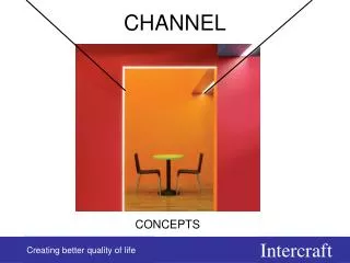
Sense Channel Node signal is provided to ADC and then to another the same pass band filter to suppress noise outside the frequency band x and is divided by two sub channels where sine and cosine components are extracted (see fig.6.4):

E N D
Sense Channel Node signal is provided to ADC and then to another the same pass band filter to suppress noise outside the frequency band x and is divided by two sub channels where sine and cosine components are extracted (see fig.6.4): Sine component of node signal (Coriolis sub channel); Cosine component of node signal (Quadrature sub channel); Coriolis control Demodulator #2 extracts the sine (Coriolis) component of the node signal. Demodulator #2 output signal is provided to regulator #2 which forms the signal proportional to angle rate (gyro out signal) and send it to output connector. The same signal is re-modulated by the cosine reference signal C1 and to sum with quadrature control signal. Quadrature control Quadrature control sub channel resembles Coriolis control one. Demodulator #3 extracts the cosine (Quadrature) component of the node signal. Demodulator #3 output signal is provided to regulator #3 which forms the signal proportional to quadrature signal and send it to re-modulation by the sine reference signal S1=sin(xt) and then to add to Coriolis control signal. The sum of two signals through DAC is provided to the compensated electrode of the resonator to drive to null node oscillation.
The Metallic Resonator CVG Design The latest achievement in gyrotechnology – micromechanical gyro is also a version of CVG, where resonator is made of some microns thickness film (quartz or silicon). One of the CVG version using metallic alloy cylindrical resonator was developed and produced in Ukrainian center for optical instrument technology. Metallic resonators CVG sensing element Ukrainian digital CVG Proximity circuit board Digital control circuit board Power circuit board Fig.11.1. Digital CVG components
Metallic Cylindrical Resonator CVG Typical Characteristics CVG25 Allan variance CVG17 Allan variance Fig.11.2. Digital CVG accuracy characteristics CVG43 Allan variance
Metallic resonator CVG manufacturing technology Metallic resonator CVG consists of sensing element, three circuit boards and casing. Sensing element in its turn consists of cylindrical resonator, base, screw to fix resonator on the base and cover under which vacuum is made as depicted in fig. 11.3. The single high technology part is resonator. It should be made of special alloy and with high geometric accuracy. This alloy should have low frequency-temperature coefficient, high and temperature stable Q-factor. Fig.6.16. The lathe for hogging workpiece. There are groups of alloys based on iron Fe and nickel (Ni) doped with different metals (for example, chromium (Cr), molybdenum (Mo), bismuth (W)) known as elinvars. One of the good materials for CVG resonator is C-300 alloy (produced by VascoMax company, USA). Base Resonator Cover Fig.11.3. CVG sensing element Cylindrical resonator manufacturing process First of all preliminary mechanical processing should be made, so called hogging, using lathe, see fig.6.16. Before accurate mechanical processing to obtain precision geometry, thermal treatment should be made to make the metal stiff under cutting. The thermal treatment process that makes the metal stiff is called hardening. Fig.11.4. Lathe for hogging workpiece
Hardening process consists of heating the workpiece to specific temperature, for C-300 alloy it is about 580-590oC, and rapid cooling. This process can be made using vacuum oven FQ-4х12-WM-1200-VG, Серия #3650, see fig.11.5. The accurate mechanical processing should be made at high precision lathe, for example, multifunctional machine tool Shoublin 140 CNC (computer numerical control), see fig.11.6. The lathe is mainly used for classical turning and is primarily intended for internal and external cylindrical and conical surfaces, as well as the flat end surfaces. Shaped surfaces were obtained either from the contoured cutting edge tool for its cross feed, or by a curved tool path along the axis of rotation of the workpiece. Modern lathes at the expense of numerical control of the tool and workpiece, as well as through the use of additional actuators of tools, can greatly expand the variety of forms of the processsing surfaces. This variety of forms can be seen in figures 11.7 and 11.8. Fig.11.5. Vacuum oven for thermal treatment Fig.11.6. Multifunctional machine tool Shaublin 140 CNC
(a) (b) Cutting depth Fig.11.7. Boring cylinder (a) and hole (b) using lathe. feed Turning fillets by combining feeds grooving process boring holes process Processing of profiled surfaces Fig.11.8. Turning shaped surfaces. Threading on a lathe
In terms of the diversity of the machined surfaces, turning moves in the direction of aggregative turning, namely the creation of multi-spindle lathes with multi-tool heads, equipped with stand-alone drives for the tool provides a variety of forms of the machined surfaces which are not relevent to the classical turning. In terms of the maximum achievable accuracy the development goes towards a very high cutting speeds and adaptive control systems with active control of the geometric accuracy of machined surfaces. As an example, figure 11.9 shows a modern machining center’s multi-tool drum. Tools Revolved head Chucking Workpiece Fig.11.9. Processing on a lathe using a multi-tool drum
585oC 585oC 210 30 210 t, min t, min 30 Fig.11.10. Temperature profile in hardening process Fig.11.11. Temperature profile in annealing process After this processing and size control operation, aging process should be made by annealing the resonator in vacuum oven. Annealing process differs from hardening process by cooling procedure. In annealing process cooling is much slow than in hardening process (see fig.11.10, 11.11). After annealing process chemical polishing process follows to smooth the surface of the resonator, to reduce its roughness by removing cutting tracks. Chemical polishing or more accurate electro-chemical polishing is process that removes material from a metallic workpiece. It is used to polish, passivate and deburr of metal parts.Typically, the workpiece is immersed in a temperature controlled bath of electrolyte and serves as the anode as it is connected to the positive terminal of a DC power supply, the negative terminal being attached to the cathode. A current passes from the anode, where metal on the surface is oxidized and dissolved in the electrolyte, to the cathode.
At the cathode, a reduction reaction occurs, which normally produces hydrogen. Electrolytes used for electro-chemical polishing are most often concentrated acid solutions having a high viscositysuch as mixtures of sulfuric acid and phosphoric acid. Other electro-chemical polishing electrolytes include mixtures of perchlorates with acetic anhydrite and methanolic solutions of sulfuric acid. Fig. 11.12 show the tank with electrodes and chemicals. To achieve electro-chemical polishing of a rough surface, the protruding parts of a surface profile must dissolve faster than the recesses. This process, referred to as anodic leveling, is achieved by a mass transport limited dissolution reaction. Anodic dissolution under electro-polishing conditions deburrs metal objects due to increased current density on corners and burrs. Fig.11.13 shows the metal surface before and after electro-chemical polishing. Fig.11.12. Electro-chemical polishing process Fig.11.13. Metal surface before (left) and after (right) electro-chemical polishing.