Download
1 / 50
500 likes | 721 Views
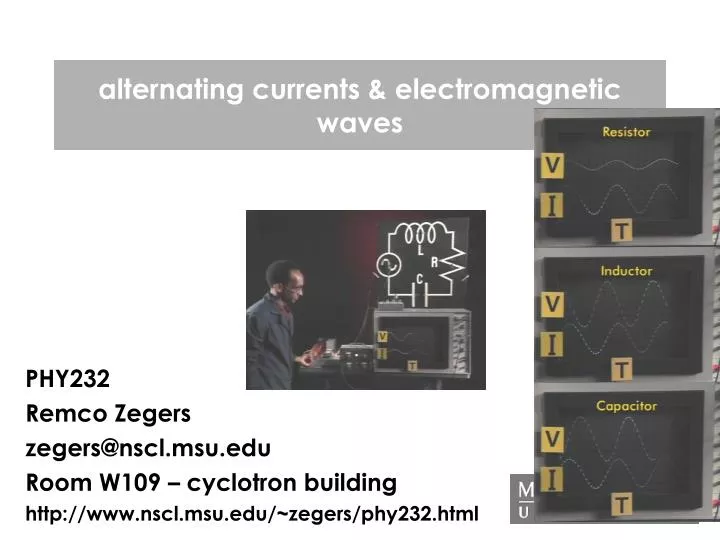
alternating currents & electromagnetic waves. PHY232 Remco Zegers zegers@nscl.msu.edu Room W109 – cyclotron building http://www.nscl.msu.edu/~zegers/phy232.html. Alternating current circuits. R. R. previously, we look at DC circuits (the voltage delivered by the source was constant).

E N D
alternating currents & electromagnetic waves PHY232 Remco Zegers zegers@nscl.msu.edu Room W109 – cyclotron building http://www.nscl.msu.edu/~zegers/phy232.html
Alternating current circuits R R • previously, we look at DC circuits (the voltage delivered by the source was constant). • Now, we look at AC circuits, in which case the source is sinusoidal. A is used in circuits to denote the difference I I V V PHY232 - Remco Zegers - alternating currents and electromagnetic waves
A circuit with a resistor R • The voltage over the resistor is the same as the voltage delivered by the source: VR(t)=V0sint=V0sin(2ft) • The current through the resistor is: IR(t)= V0/Rsint • Since V(t) and I(t) have the same behavior as a function of time, they are said to be ‘in phase’. • V0 is the maximum voltage • V(t) is the instantaneous voltage • is the angular frequency; =2f f: frequency (Hz) • SET YOUR CALCULATOR TO RADIANS WHERE NECESSARY IR(A) I V0=10 V R=2 Ohm =1 rad/s V(t)=V0sint PHY232 - Remco Zegers - alternating currents and electromagnetic waves
lon-capa • you should now do problem 1 from set 7. PHY232 - Remco Zegers - alternating currents and electromagnetic waves
rms currents/voltages • To understand energy consumption by the circuit, it doesn’t matter what the sign of the current/voltage is. We need the absolute average currents and voltages (root-mean-square values) : • Vrms=Vmax/2 • Irms=Imax/2 • The following hold: • Vrms=IrmsR • Vmax=ImaxR IR(A) Vrms |IR|(A) |VR|(V) Irms PHY232 - Remco Zegers - alternating currents and electromagnetic waves
power consumption by an AC circuit • We already saw (DC): • P=VI=V2/R=I2R • For AC circuits with a single resistor: • P(t)=V(t)*I(t)=V0I0sin2t • The average power consumption: • Pave=Vrms*Irms=V2rms/R=I2rmsR • Pave=(Vmax/2)(Imax/2)= ImaxVmax/2 Vrms |IR|(A) |VR|(V) Irms P(W) PHY232 - Remco Zegers - alternating currents and electromagnetic waves
vector representation V0 =t V time (s) -V0 The voltage or current as a function of time can be described by the projection of a vector rotating with constant angular velocity on one of the axes (x or y). PHY232 - Remco Zegers - alternating currents and electromagnetic waves
I(t)=V(t)=0 t t I(t)=5A V(t)=10 V V(t)=-10V I(t)=-5A t phasors I(t), V(t) are in phase, so point in the same direction IR(A) =t I(t) V(t) t The instantaneous current and voltage over R are the projections on the t-axis (horizontal axis) of vectors rotating with ang. frequency . The length of the vectors indicate the maximum current or voltage. PHY232 - Remco Zegers - alternating currents and electromagnetic waves
Since the V-vector is shorter than the R vector, R=V/I<1 Ohm question t V(t) I(t) • Given a phasor diagram for a single resistor in circuit. • If the voltage scale is V and current scale Ampere, • then the resistor has a resistance • < 1 Ohm • > 1 Ohm • 1 Ohm PHY232 - Remco Zegers - alternating currents and electromagnetic waves
A circuit with a single capacitor C I IC(A) V(t)=V0sint Vc= V0sint Qc=CVc=CV0sint Ic=Qc/t= CV0cost= CV0sin(t+/2) So, the current peaks ahead in time (earlier) of the voltage There is a difference in phase of /2 (900) why? When there is not much charge on the capacitor it readily accepts more and current easily flows. However, the E-field and potential between the plates increase and consequently it becomes more difficult for current to flow and the current decreases. If the potential over C is maximum, the current is zero. PHY232 - Remco Zegers - alternating currents and electromagnetic waves
phasor diagram for capacitive circuit IC(A) =t I(t) V(t) t Note: Imax= CV0 For a resistor we have I=V0/R so ‘1/C’ is similar to ‘R’ And we write: I=V/Xc with Xc= 1/C the capacitive reactance Units of Xc are Ohms. The capacitive reactance acts as a resistance in this circuit. PHY232 - Remco Zegers - alternating currents and electromagnetic waves
power consumption in a capacitive circuit There is no power consumption in a purely capacitive circuit: Energy (1/2CV2) gets stored when the (absolute) voltage over the capacitor is increasing, and released when it is decreasing. Pave = 0 for a purely capacitive circuit PHY232 - Remco Zegers - alternating currents and electromagnetic waves
question =t I(t) V(t) t • The angle between the current vector and voltage • vector in a phasor diagram for a capacitive circuit is • 00 • 450 • 900 • 1800 PHY232 - Remco Zegers - alternating currents and electromagnetic waves
A circuit with a single inductor L IL(A) I V(t)=V0sint VL= V0sint=LI/t IL=-V0/(L)cost= V0 /(L)sin(t-/2) (no proof here: you need calculus…) So, the current peaks later in time than the voltage There is a difference in phase of /2 (900) why? As the potential over the inductor rises, the magnetic flux produces a current that opposes the original current. The voltage across the inductor peaks when the current is just beginning to rise, due to this tug of war. PHY232 - Remco Zegers - alternating currents and electromagnetic waves
phasor diagram for inductive circuit IL(A) =t t I(t) V(t) Note: Imax= V0/(L) For a resistor we have I=V0/R so ‘L’ is similar to ‘R’ And we write: I=V/XL with XL= L the inductive reactance Units of XL are Ohms. The inductive reactance acts as a resistance in this circuit. PHY232 - Remco Zegers - alternating currents and electromagnetic waves
power consumption in an inductive circuit There is no power consumption in a purely inductive circuit: Energy (1/2LI2) gets stored when the (absolute) current through the inductor is increasing, and released when it is decreasing. Pave = 0 for a purely inductive circuit PHY232 - Remco Zegers - alternating currents and electromagnetic waves
question • The inductive reactance (and capacitive reactance) are just like the resistance of a normal resistor, I.e. if I know the inductive reactance, I can calculate the current at any time given the voltage using I=V/XL. • a) True • b) False answer: False; it tells something about maximum currents and voltages, but ignores the phases involved. PHY232 - Remco Zegers - alternating currents and electromagnetic waves
Combining the three: the LRC circuit L C R • Things to keep in mind when analyzing this system: • 1) The current in the system has the same value everywhere I=I0sin(t-) • 2) The voltage over all three components is equal to the source voltage at any point in time: V(t)=V0sin(t) I V(t)=V0sint PHY232 - Remco Zegers - alternating currents and electromagnetic waves
An LRC circuit VR I • For the resistor: VR=IRR and VR and IR=I are in phase • For the capacitor: Vc=IXc and Vc lags Ic=I by 900 • For the inductor: VL=IXL and VL leads IL=I by 900 • at any instant: VL+Vc+VR=V0sin(t), that is the total voltage Vtot is the vector addition of the three individual components I Vtot VR VL VC =t t VL VC PHY232 - Remco Zegers - alternating currents and electromagnetic waves
impedance VR VR • Vtot= VL+Vc+VR (vectors) • Vtot=[VR2+(|VL|-|VC|)2]= [ (IR)2+(IXL-IXC)2]=I[R2+(XL-Xc)2] • define X=XL-Xc : reactance of an RLC circuit • define Z=[R2+(XL-Xc)2]= [R2+X2] : impedance of RLC circ. • Vtot=IZ & I=Vtot/Z looks like Ohms law Vtot VL VL t t vector sum VL+VC VC VC PHY232 - Remco Zegers - alternating currents and electromagnetic waves
phase angle VR VR • The current I and the voltage Vtot are out of phase by an angle . This angle can be calculated with: • tan=opposite/adjacent=(|VL|-|Vc|)/VR=X/R I Vtot Vtot VL VL =t t t vector sum VL+VC VC VC PHY232 - Remco Zegers - alternating currents and electromagnetic waves
VR Vtot VL vector sum VL+VC=0 t VC question • If the maximum voltage over the capacitor equals the maximum voltage over the inductor, the difference in phase between the voltage over the whole circuit and the voltage over the resistor is: • a) 00 • b)450 • c)900 • d)1800 PHY232 - Remco Zegers - alternating currents and electromagnetic waves
power consumption by an LRC circuit • Even though the capacitor and inductor do not consume energy on the average, they affect the power consumption since the phase between current and voltage is modified. • P=I2rmsR=IrmsVR • VR=Vrmscos (since cos=VR/Vtot) • So: P=VrmsIrmscos • cos: power factor of a circuit VR Vtot VL t VL+VC VC PHY232 - Remco Zegers - alternating currents and electromagnetic waves
lon-capa • you should now do problem 4 from LON-CAPA 7 PHY232 - Remco Zegers - alternating currents and electromagnetic waves
Given: R=250 Ohm L=0.6 H C=3.5 F f=60 Hz V0=150 V example L C R • questions: • a) what is the angular frequency of the system? • b) what are the inductive and capacitive reactances? • c) what is the impedance, what is the phase angle • d) what is the maximum current and peak voltages over each element • Compare the algebraic sum of peak voltages with V0. Does this make sense? • e) make the phasor diagram. Include I,VL,VC,VR,Vtot, . Assume VR is in the first quadrant. • f) what are the instantaneous voltages and rms voltages over each element. Consider Vtot to have zero phase. • g) power consumed by each element and total power consumption I V(t)=V0sint PHY232 - Remco Zegers - alternating currents and electromagnetic waves
Given: R=250 Ohm L=0.6 H C=3.5 F f=60 Hz V0=150 V answers • a) angular frequency of the system? • =2f=260=377 rad/s • b) Reactances? • XC=1/C=1/(377 x 3.5x10-6)=758 Ohm • XL= L=377x0.6=226 Ohm • c) Impedance and phase angle • Z=[R2+(XL-Xc)2]=[2502+(226-758)2]=588 Ohm • =tan-1[(XL-XC)/R)=tan-1[(226-758)/250]=-64.80 (or –1.13 rad) • d) Maximum current and maximum component voltages: • Imax=Vmax/Z=150/588=0.255 A • VR=ImaxR=0.255x250=63.8 V • VC=ImaxXC=0.255x758=193 V • VL=ImaxXL=0.255x266=57.6 V • Sum: VR+VC+VL=314 V. This is larger than the maximum voltage delivered by the source (150 V). This makes sense because the relevant sum is not algebraic: each of the voltages are vectors with different phases. PHY232 - Remco Zegers - alternating currents and electromagnetic waves
e) the phasor diagram • Imax=Vmax/Z=0.255 A • VR=ImaxR=63.8 V • VC=ImaxXC=193 V • VL=ImaxXL=57.6 V • =-64.80 (or –1.13 rad) • Vtot=150 V VR I VL t Vtot =t VL+VC start with VR (in first quadrant). The I vector is in the same direction. VC vector is perpendicular to VR, 900 later in time (counter-clockwise). VL is perpendicular to VR, 900 faster in time (clockwise). Add VL and VC as vectors, and add the results to VR as vectors to make Vtot. The angle between the horizontal x-axis and Vtot is the angle t. The angle between I (or VR) and Vtot is the phase angle . VC PHY232 - Remco Zegers - alternating currents and electromagnetic waves
Imax=Vmax/Z=0.255 A • VR=ImaxR=63.8 V • VC=ImaxXC=193 V • VL=ImaxXL=57.6 V • =-64.80 (or –1.13 rad) • Vtot=150 V answers • f) instantaneous voltages over each element (Vtot has 0 phase)? • start with the driving voltage V=V0sint=Vtot • VR(t)=63.8sin(t+1.13) (note the phase relative to Vtot) • VC(t)=193sin(t-0.44) phase angle : 1.13-/2=-0.44 • VL(t)=57.6sin(t+2.7) phase angle : 1.13+/2=2.7 • rms voltages over each element? • VR,rms=63.8/2=45.1 V • VC,rms=193/2=136 V • VL,rms=57.6/2=40.7 V PHY232 - Remco Zegers - alternating currents and electromagnetic waves
answers • g) power consumed by each element and total power consumed? • PC=PL=0 no energy is consumed by the capacitor or inductor • PR=Irms2R=(Imax/2)2R=0.2552R/2=0.2552*250/2)=8.13 W • or: PR=Vrms2/R=(45.1)2/250=8.13 W (don’t use Vrms=V0/2!!) • or: PR=VrmsIrmscos=(150/2)(0.255/2)cos(-64.80)=8.13 W • total power consumed=power consumed by resistor! PHY232 - Remco Zegers - alternating currents and electromagnetic waves
lon-capa • you should now try problem 6 of lon-capa set 7, except for the last part PHY232 - Remco Zegers - alternating currents and electromagnetic waves
LRC circuits: an overview VR I Vtot • Reactance of capacitor: Xc= 1/C • Reactance of inductor: XL= L • Current through circuit: same for all components • ‘Ohms’ law for LRC circuit: Vtot=IZ • Impedance: Z=[R2+(XL-Xc)2] • phase angle between current and source voltage: tan=(|VL|-|Vc|)/VR=(XL-Xc)/R • Power consumed (by resistor only): P=I2rmsR=IrmsVR P=VrmsIrmscos • VR=ImaxR in phase with current I, out of phase by with Vtot • VC=ImaxXC behind by 900 relative to I (and VR) • VL=ImaxXL ahead of 900 relative to I (and VR) VL =t t vector sum VL+VC VC PHY232 - Remco Zegers - alternating currents and electromagnetic waves
quiz (extra credit) • The sum of maximum voltages over the resistor, capacitor and inductor in an LRC circuit cannot be higher than the maximum voltage delivered by the source since it violates Kirchhoff’s 2nd rule (sum of voltage gains equals the sum of voltage drops). • a) true • b) false answer: false The maximum voltages in each component are not achieved at the same time! PHY232 - Remco Zegers - alternating currents and electromagnetic waves
Resonances in an RLC circuit • If we chance the (angular) frequency the reactances will change since: • Reactance of capacitor: Xc= 1/C • Reactance of inductor: XL= L • Consequently, the impedance Z=[R2+(XL-Xc)2] changes • Since I=Vtot/Z, the current through the circuit changes • If XL=XC (I.e. 1/C= L or2=1/LC), Z is minimal, I is maximum) • = (1/LC) is the resonance angular frequency • At the resonance frequency =0 (see question on slide 23) Z I 0 PHY232 - Remco Zegers - alternating currents and electromagnetic waves
example Using the same given parameters as the earlier problem, what is the resonance frequency? Given: R=250 Ohm L=0.6 H C=3.5 F f=60 Hz V0=150 V = (1/LC)=690 rad/s f= /2=110 Hz PHY232 - Remco Zegers - alternating currents and electromagnetic waves
question • An LRC circuit has R=50 Ohm, L=0.5 H and C=5x10⁻³ F. An AC source with Vmax=50V is used. If the resistance is replaced with one that has R=100 Ohm and the Vmax of the source is increased to 100V, the resonance frequency will: • a) increase • b)decrease • c) remain the same answer c) the resonance frequency only depends on L and C PHY232 - Remco Zegers - alternating currents and electromagnetic waves
loncapa • You should now try question 6, part 7 and question 5 of lon-capa set 7. PHY232 - Remco Zegers - alternating currents and electromagnetic waves
transformers transformers are used to convert voltages to lower/higher levels PHY232 - Remco Zegers - alternating currents and electromagnetic waves
transformers primary circuit with Np loops in coil secondary circuit with Ns loops in coil Vp Vs iron core If an AC current is applied to the primary circuit: Vp=-NpB/t The magnetic flux is contained in the iron and the changing flux acts in the secondary coil also: Vs=-NsB/t Therefore: Vs=(Ns/Np)Vp if Ns<Np then Vs<Vp A perfect transformer is a pure inductor (no resistance), so no power loss: Pp=PS and VpIp=VsIs ; if Ns<Np then Vs<Vp and IS>Ip PHY232 - Remco Zegers - alternating currents and electromagnetic waves
question a transformer is used to bring down the high-voltage delivered by a powerline (10 kV) to 120 V. If the primary coil has 10000 windings, a) how many are there in the secondary coil? b) If the current in the powerline is 0.1 A, what is the maximum current at 120 V? • Vs=(Ns/Np)Vp or Ns=(Vs/Vp)Np = 120 windings • VpIp=VsIs so Is=VpIp/Vs=8.33 A PHY232 - Remco Zegers - alternating currents and electromagnetic waves
question • Is it more economical to transmit power from the power station to homes at high voltage or low voltage? • a) high voltage • b) low voltage answer: high voltage If the voltage is high, the current is low If the current is low, the voltage drop over the power line (with resistance R) is low, and thus the power dissipated in the line ([V]2/R=I2R) also low PHY232 - Remco Zegers - alternating currents and electromagnetic waves
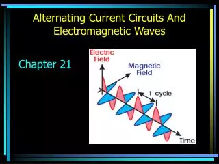
electromagnetic waves • James Maxwell formalized the basic equations governing electricity and magnetism ~1870: • Coulomb’s law • Magnetic force • Ampere’s Law (electric currents make magnetic fields) • Faraday’s law (magnetic fields make electric currents) • Since changing fields electric fields produce magnetic fields and vice versa, he concluded: • electricity and magnetism are two aspects of the same phenomenon. They are unified under one set of laws: the laws of electromagnetism PHY232 - Remco Zegers - alternating currents and electromagnetic waves
electromagnetic waves Maxwell found that electric and magnetic waves travel together through space with a velocity of 1/(00) v=1/(00)=1/(4x10-7 x 8.85x10-12)=2.998x10⁸ m/s which is just the speed of light (c) PHY232 - Remco Zegers - alternating currents and electromagnetic waves
electromagnetic waves can be used to broadcast… • Consider the experiment performed by Herz (1888) I Herz made an RLC circuit with L=2.5 nH, C=1.0nF The resonance frequency is = (1/LC)=6.32x108 rad/s f= /2=100 MHz. Recall that the wavelength of waves =v/f=c/f=3x108/100x106=3.0 m wavelength: =v/f PHY232 - Remco Zegers - alternating currents and electromagnetic waves
charges and currents vary sinusoidally in the primary and secondary circuits. The charges in the two branches also oscillate at the same frequency f He then constructed an antenna dipole antenna I PHY232 - Remco Zegers - alternating currents and electromagnetic waves
++++++ ---------- ---------- ++++++ producing the electric field wave antenna PHY232 - Remco Zegers - alternating currents and electromagnetic waves
++++++ ---------- I I I ---------- ++++++ I producing the magnetic field wave E and B are in phase and E=cB with c: speed of light The power/m2=0.5EmaxBmax/0 The energy in the wave is shared between the E-field and the B-field antenna PHY232 - Remco Zegers - alternating currents and electromagnetic waves
question Can a single wire connected to the + and – poles of a DC battery act as a transmitter of electromagnetic waves? • yes • no answer: no: there is no varying current and hence no wave can be made. PHY232 - Remco Zegers - alternating currents and electromagnetic waves
c=f PHY232 - Remco Zegers - alternating currents and electromagnetic waves
lon-capa • now try questions 2 and 7 from set 7. PHY232 - Remco Zegers - alternating currents and electromagnetic waves
R L I V The coil opposes the flow of current due to self-inductance, so the current cannot immediately become the maximum I=V/R. It will slowly rise to this value quiz (extra credit) • At t=0, the switch is closed. Shortly after that: • a) the current slowly increases from I=0 to I=V/R • b) the current slowly decreases from I=V/R to I=0 • c) the current is a constant I=V/R PHY232 - Remco Zegers - alternating currents and electromagnetic waves