Download
1 / 64
640 likes | 777 Views
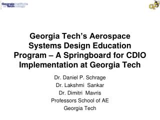
System Safety Risk Management: An Autonomous UAV Example from a Course on Safety By Design and Flight Certification. Dr. Daniel P. Schrage Professor and Director, CASA and CERT School of Aerospace Engineering Georgia Institute of Technology Atlanta, GA 30332-0150. Presentation Outline.

E N D
System Safety Risk Management: An Autonomous UAV Example from a Course on Safety By Design and Flight Certification Dr. Daniel P. Schrage Professor and Director, CASA and CERT School of Aerospace Engineering Georgia Institute of Technology Atlanta, GA 30332-0150
Presentation Outline • Overview of Georgia Tech graduate program in Aerospace Systems Design • Brief description of the Safety By Design and Flight Certification Course • Example from Safety Course for an Autonomous Unmanned Aerial Vehicle (UAV) – The GTMAX
Georgia Tech Practice-Oriented M.S. Program in Aerospace Systems Design Summer Semester I Semester II IPPD Methods/Techniques Integrated Propulsion Disciplinary Courses Special Product/Process Systems Development Design Project Safety By Design Applied Applied Systems Systems Design I Design II Design I Design II Design Modern Modern Product Seminars Design Design Life Cycle Methods I Methods II Management IPPD Tools/Infrastructure Internships Mathematics (2 Required) Other Electives Legend: Core Classes Elective Classes
Safety By Design and Flight Certification Course • First taught in 1998 as a project oriented course to orient students on the role of safety by design and flight certification in the design iteration process • Course builds on the Integrated Product/Process Development (IPPD) through Robust Design Simulation (RDS) environment created in the Georgia Tech Aerospace Systems Design Laboratory (ASDL) • Course taught in the summer semester to allow students to analyze the designs they developed during the fall and spring semesters (Fixed Wing,V/STOL Rotorcraft, Space, and Missiles) • Course has been continuously improved each year to address more of the issues in moving to a risk based managed process • Course has sought to incorporate user friendly tools for System Reliability Prediction, FTA, FMEA and Markov Analysis • Emphasis on the course taught this summer was on the interaction of Hardware, Software, and Liveware (Human) reliabilities & partnerships with industry and government
Course Projects for Summer 2002 • Quiet Supersonic Aircraft – in conjunction with Gulfstream Aerospace Corporation • The ICBM Peacekeeper as a Commercial Launch Vehicle – in conjunction with the FAA Space Systems Development Division • A VTOL Personal Air Vehicle (PAV) – in conjunction with the NASA PAV Evaluation program • *An Autonomous UAV: GTMAX – in conjunction with the DARPA Software Enabled Control (SEC) program and the GT Entry in the International Aerial Robotics Competition (IARC) * Example to be illustrated
Development of a Certification Plan(ARP 4754:Cert Considerations For Highly-Integ or Complex Aircraft Systems) • Each Plan should include: • A functional and operational description of the system and the aircraft on which the system will be installed • A statement of the relationship of this certification plan to any other relevant system certification plans • A summary of the functional hazard assessment (aircraft hazards, failure conditions, and classification) • A summary of the preliminary system safety assessment (system safety objectives & preliminary system development assurance levels) • A description of any novel or unique design features that are planned to be used in meeting the safety objectives • A description of the new technologies or new technology applications to be implemented • The system certification basis including any special conditions • The proposed methods of showing compliance with the certification basis • A list of the data to be submitted and the data to be retained under configuration control, along with a description or sample of data formats • The approximate sequence and schedule for certification events
DO DO DO - - - 178B/160D 178B 178B AIRCRAFT/SPACECRAFT ARP 4754 ARP 4754 ARP 4754 SYSTEM DESIGN ARP 4761 ARP 4761 ARP 4761 RELIABILITY SAFETY PREDICTION PREDICTION ANALYSIS FHA/FTA TECHNIQUES Technology Insert. Other PSSA Methods TIF/TIES ? PREDICTION CRITICALITY PROGRAMS MATRIX SYSTEM RELIABILITY RELIABILITY NO (PRISM) SIMULATION MARKOV ANALYSIS APPLY (MEADEPS) SATISFIED? PROBABILISTIC ASSESSMENT YES (CRYSTAL BALL) The Overall GT Safety By Design Approach AIRCRAFT/SPACECRAFT SYSTEM DESIGN Aircraft/Spacecraft FHA/FTA Safety Goals RELIABILITY SAFETY PREDICTION PREDICTION ANALYSIS System FHA/FTA FHA/FTA TECHNIQUES Technology Insert. Other PSSA Methods Other PSSA Methods TIF/TIES ? PREDICTION CRITICALITY CRITICALITY PROGRAMS MATRIX MATRIX SYSTEM RELIABILITY SYSTEM RELIABILITY RELIABILITY NO (PRISM) (PRISM) SIMULATION MARKOV ANALYSIS MARKOV ANALYSIS APPLY (MEADEPS) (MEADEPS) SATISFIED? PROBABILISTIC ASSESSMENT PROBABILISTIC ASSESSMENT YES (CRYSTAL BALL) (CRYSTAL BALL)
SBD Process Overview Detailed Design Design Validation & Verification Concept Development Preliminary Design • Aircraft FHA • Functions • Hazards • Effects • Classifications • System FHA • Functions • Hazards • Effects • Classifications PSSA SSA • System FTAs • Qualitative • Failure Rates System FMEAs FMES • System FTA • Qualitative • Subsystem Budgets • DD • MA • Aircraft FTA • Qualitative • System Budgets • Intersystem Dependencies Particular Risk Analysis CCA Common Mode Analysis Zonal Safety Analysis
GTMaxPreliminary Safety Assessment and Certification Plan Han Gil ChaeAdeel KhalidKayin CannonColin PouchetHenrik B. Christophersen
Overview • Introduction • General facts about GTMax • GTMax Certification • General Information of UAV Certification • Analysis for particular system • Human Errors • Proposed system improvement • Proposed Certification plan • Conclusions
Introduction System Description System Requirements
Originally developed for aerial pest control Modified for DARPA SEC Program and for Aerial Robotics Test bed for Manned Vehicle Electronic System GTMax : Development
Software Enabled Control (SEC) The objective of SEC is to co-develop advanced real-time control system algorithms and the software services and infrastructure necessary to implement them on distributed embedded processors in a robust and verifiable way Dr. John Bay DARPA/IXO
DARPA SEC Participants • Open Control Platform (OCP) Developers: -Georgia Tech - Boeing Phantom Works - UC Berkeley -Honeywell Technology Labs • SEC Technology Developers (Active State Modelers, On Line Control Customization,Coordinated Multi-Modal Control, High Confidence Software Control Systems): -Georgia Tech - UC Berkeley - Rockwell Collins - Cornell - MIT - Northrop Grumman Corp - Cal Tech - Draper Labs - Honeywell Labs - U of Min - Vanderbilt - OGI - Stanford • University Led Experiments (Rotary Wing): Georgia Tech • Industry Led Experiments (Fixed Wing): Boeing Phantom Works
The Georgia Tech GTMAX : A Truly Modular Open System Testbed • The Georgia Tech GTMAXconsists of • The Yamaha RMAX Remotely Piloted Helicopter: a rugged, proven air vehicle which is becoming the vehicle testbed choice for VTOL UAV autonomous vehicle research • The Georgia Tech Modular Avionics Package: built for reconfigurability, growth and easy upgrade • The Boeing - Georgia Tech OCP: a Real Time CORBA based open system software architecture • As a system the GTMAX provides an excellent resource for the UAV community for developing and evaluating UAV technologies, both hardware and software, as well as Home Security Experiments
GTMAX : Vehicle Specifications (mm) Weight Gross Weight : 204.6 lb Empty Weight : 127.6 lb Payload : 66 lb Engine Gasoline 2-Cylinder Water Cooled Power output : 21Hp Performance Fuel : 6L (1.6 gal) Endurance : 60 min 1800 3115 1080 720 3630
RC Transmitter GT Research UAV: GTMAX GPS GPS Reference Georgia Tech Onboard Avionics Data Link I Data Link I Ground Computer(s) And Network GEORGIA TECH Boeing-GT OCP Ethernet Data Link II Data Link II Ground Control Station 3x RS-232 Serial Yamaha Attitude Control System (YACS) RC Receiver YAMAHA Actuators On-board Avionics Safety Pilot
Onboard Avionics Hardware Architecture Ext Power Magneto-meter Power Dist Sonar Altimeter Servo- Interface Radar Altimeter Computer #1 IMU Video Camera, Radar and Possibly Lidar to be installed this summer Computer #2 D-GPS Wireless Serial Ethernet Hub Wireless Ethernet Serial Data Ethernet Power
GTMAX Avionics HW Integration • GTMAX hardware is packaged into exchangeable modules: • Flight Computer Module • GPS Module • Data Link Module • IMU/Radar Module • Unused Module (Growth) • Sonar/Magnetometer Assemblies • Power Distribution System • Each module has self-contained power regulation and EMI shielding • Shock-mounted main module rack
GTMAX Hardware Integration • Power System • On-board generator outputs 12V DC, 10 A • Power source hot-swappable between on-board and external • Each module is powered via individual circuit breakers • Interfacing and Wiring • Interface Types: RS-232 Serial, Ethernet, 12V DC • All interfaces on module back-sides • Aviation-quality wiring harness
Open Control Platform Motivation • Limitations of State-of-the-Art • Complex Control Systems: • Tightly coupled • Difficult to adapt or evolve • Complex, inflexible data • interchange • Computationally limited • Closed, proprietary systems • Desired Capabilities: • Adaptibility and dynamic • reconfigurability • Plug-and-play extensibility, • component interchangeability • Real-time quality of service • Interoperability, distributed • communication • Openness
Sensors Serial Interface GPS IMU Magnetometer sonar Vehicle Serial Interface I/O Component RMAX Attitude sensors receiver commands Vehicle Health Navigation Module Component Controller Component RMAX Actuator demultiplexer Actuator Serial Interface Boeing-GIT Baseline Open Control Platform (OCP) Software Implementation on the GTMAX Controls API Input Port Controls API Output Port timeout_in 100 Hz Timer DataLink Interface Ethernet “Serial” Port Input datalink ports read @ 100 Hz Serial port NavData_out ControlData_out Ethernet “Serial” Port 1 Hz & 10 Hz m0 written at 10 Hz m1 written at 1 Hz Serial port 1 Hz & 10 Hz 50 Hz 100 Hz ControlData_in NavData_in NavControl_in 50 Hz 50 Hz NavControl_out
Emergency ? Mission Intelligence Flow for GT Research Situation Awareness Mission Planning Fault Tolerant Control Obstacle/Target Tracking Mode Selection Mode Switching Yes Obstacle/Target Identification Continue Mission Flight Control System No Obstacle/Target Detection UAV Diagnostics Sensors Sensor Fusion
15 min Fly Autonomously T/O (manually) 3Km Get Information from the Inside GTMax : Aerial Robotics Mission & SEC Scenario Identify Structure No Need to Return after the Mission
GTMax Certification Certification Basis Analysis (Functional, FHA, PSSA) Human Errors Strategy for achieving compliance Sequence of certification events
FAA Certification Design Production Operation Type Design Approval Quality Assurance Approval Type Design Conformity Continued Airworthiness Type Certificate Production Certificate Airworthiness Certificate Defect found in operation
No Certification Basis for UAVs System Design/Analysis - AC 25.1309-1A Safety Assessment - SAE APR4761 Rotorcraft - FAR 27 Suggested Regulations Certification Basis
Certification basis? • Presently no certification basis for unmanned aircraft. • Unmanned vs. manned aircraft: • Increased reliance on electronic flight control systems in unmanned aircraft • Safety = threat to persons and property outside aircraft • Flight over populated areas vs. isolated areas • Ground Control System
Suggested Regulations • Flight crewmember(s) on the ground • Safety equipment for occupants not required • Impact protection for occupants • Safety belts • Oxygen • Warning lights • Flight Control System Certification • Ground Control System Certification • Categories of unmanned aircraft
Certification basis Amended FARs • FAR Part 1: Definitions and Abbreviations • FAR Part 21: Certification Procedures for Products and Parts • FAR Part 27: Airworthiness Standards: Normal Category Rotorcraft • FAR Part 33: Airworthiness Standards: Aircraft Engines • FAR Part XX: Airworthiness Standards: Electronic Flight Control Systems for Unmanned Aircraft • FAR Part XX: Airworthiness Standards: Ground Control Systems for Unmanned Aircraft
Functional Analysis • Top Level
Manage Organization • Manage Operation • Manage Personnel • Manage finances • Manage sales/marketing • Manage supporting equipment/facilities • Maintain Equipment • Maintain mission vehicle(s) • Maintain Ground Station Equipment • Maintain Supporting Equipment Functional Analysis
Receive Mission Assignment Functional Analysis
Prepare for mission • Verify readiness of UAV • Create flight plan • File NOTAM • Verify that all necessary equipment is loaded and ready • Obtain/sign release form • Depart for launch site Functional Analysis
Execute Mission (UAV) Functional Analysis
Execute Mission (GCS) Functional Analysis
FHA & FTA : Flight Control as Critical System Safety Subsystem • Control System (Collective) Mechanical System Electronic System
Loss of Collective Pitch Loss of Collective Pitch Control capability Control capability Loss of Actuator Loss of Mechanical Capability Linkage Capability 1E-6 Failure of Mechanical Loss of Electiricity Component of Actuator Loss of steering Loss of steering commands from commands from 1E-5 Remote Control Flight Control Receiver Computer To Electronic System Loss of Battery Failure of Wire Capability Harness Failure of On-Board Failure of Ground System Station FHA & FTA : Mechanical System
Loss of steering commands Loss of steering commands from Flight Control from Flight Control Computer Computer To Mechanical System Heartbeat Monitor Loss of steering Failure of Heartbeat Loss of steering Loss of steering switches incorrectly commands from Monitor to switch to commands from commands from to Backup Contr. Main Computer Backup Controller Backup Controller Backup Controller 1E-4 3E-3 1E-3 1E-4 Failure of Main Computer to Internal failure in discontinue sending Heartbeat Monitor heartbeats. 1E-3 1E-4 FHA & FTA : Electronic System
What for ? System failure rate modeling Markov analysis Monte Carlo Simulation Easy ? ü ü Database ü Redundancy ü ü Multiple Events ü Distribution Fuctions ü PSSA : Software Exploration Prism MEADEP Crystal Ball
Fault Tree based on FHA PRISM for Mech. Components Markov Analysis for Mechanical System & Electronic System Mech. Monte Carlo Simulation for Whole System Elec. PSSA : Strategy
PSSA : Prism modeling • Mechanical components • Prism Database • Total Failure Rate - 1.76 E-3/Op. hr
PSSA : Markov Analysis • Mechanical System • MTTF - 6023.275 /hr • Reliability - 93.57 hr
PSSA : Markov Analysis • Electronic System • MTTF - 1000.249 /hr • Reliability - 90.48 hr
Fault Tree from FHA Simplified Block Diagram Actuator Capability Steering command from Remote Control Receiver On-Board System l5 Ground System l6 Electricity l1 Mechanical Component of Actuator Battery Capability l2 Wire Harness l3 Mechanical Linkage Capability l7 Steering commands From Flight Control Computer l4 PSSA : Monte Carlo Simulation loverall = l1 + l2 + l3 + (l5 + l6) ×l4 + l7
1E-5 1E-6 1E-5 1E-5 1E-5 1E-6 Actuator Capability Steering command from Remote Control Receiver 1E-6 • Same order as Inputs On-Board System Ground System Overlay Chart Electricity Frequency Comparison .017 Mechanical Component of Actuator Battery Capability Wire Harness Mechanical Linkage Capability • Normal curve fit gives • m = 3.1×10⁻⁵ • s = 7.0 ×10⁻⁵ .012 Steering commands From Flight Control Computer .008 .004 .000 0.00290 0.00300 0.00310 0.00320 0.00330 PSSA : Monte Carlo Simulation
Reliability Goal LOAFlight Control= 1E-5 PSSA : Reliability Goals 10 / 100,000 flight hrs = 1E-4 / flight hr 10% Human error plays significant roll in UAV 60% - Mechanical system failures - “Other” external causes General Aviation Loss Of Aircraft (LOA)
- Mission planner - Ground control - Maintenance Human Errors : Introduction • Direct or Indirect • Intentional or Unintentional • Flying into Electrical Lines
Better Working Environment Increased Worker Reliability Increased Worker Safety Reduced Delays Due to Injury Increased ROA Reliability Increased Safety of ROA and Environment Increased Mission Success Human Errors : Human Safety and Reliability
Human Errors : Working Environment • Some important factors and issues Documentation - Stay 500 feet from power lines Information - There are power lines here Communication - We should move away Training - What do I do now? Workload - What? I’m busy Visual/Aural Alerts - Warning!