Download
1 / 66
680 likes | 836 Views
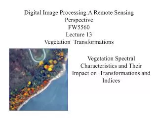
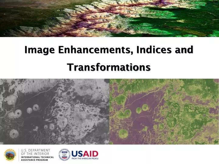
Image Enhancements, Indices and Transformations. Remote Sensing Process. Transmission, Reception, and Processing (E). (A) Energy Source or Illumination . Recording of Energy by the Sensor (D). Interpretation and Analysis (F). Radiation and the Atmosphere (B). Application (G).

E N D
Remote Sensing Process Transmission, Reception, and Processing (E) (A) Energy Source or Illumination Recording of Energy by the Sensor (D) Interpretation and Analysis (F) Radiation and the Atmosphere (B) Application (G) Interaction with the Target (C) Reference: CCRS/CCT
Remote Sensing Process Transmission, Reception, and Processing (E) (A) Energy Source or Illumination Recording of Energy by the Sensor (D) Interpretation and Analysis (F) (B) Radiation and the Atmosphere Application (G) Interaction with the Target (C) Reference: CCRS/CCT
Remote Sensing Process Transmission, Reception, and Processing (E) (A) Energy Source or Illumination Recording of Energy by the Sensor (D) Interpretation and Analysis (F) (B) Radiation and the Atmosphere (C) Interaction with the Target Application (G) Reference: CCRS/CCT
Remote Sensing Process Transmission, Reception, and Processing (E) (A) Energy Source or Illumination (D) Recording of Energy by the Sensor Interpretation and Analysis (F) (B) Radiation and the Atmosphere (C) Interaction with the Target Application (G) Reference: CCRS/CCT
Remote Sensing Process (A) Energy Source or Illumination (D) Recording of Energy by the Sensor Interpretation and Analysis (F) (B) Radiation and the Atmosphere (E) Transmission, Reception, and Processing (C) Interaction with the Target Application (G) Reference: CCRS/CCT
Remote Sensing Process (A) Energy Source or Illumination (E) Transmission, Reception, and Processing (D) Recording of Energy by the Sensor Interpretation and Analysis (F) (B) Radiation and the Atmosphere (F) Interpretation and Analysis (C) Interaction with the Target Reference: CCRS/CCT
Remote Sensing Process Energy Source or Illumination (A) Recording of Energy by the Sensor (D) Transmission, Reception, and Processing (E) Interpretation and Analysis (F) Radiation and the Atmosphere (B) (G) Application Interaction with the Target (C) Reference: CCRS/CCT
Carbon Management Aviation Energy Management Public Health Coastal Management Water Management Homeland Security Disaster Management Agricultural Efficiency Ecological Forecasting Invasive Species Air Quality Applications
Image enhancement Alteration of the image in such a way that the information contained in the image is easier to visually interpret or systematically analyze
Types of image enhancement • Radiometric enhancement • Spatial enhancement • Spectral enhancement
Types of image enhancement • Radiometric enhancement • Spatial enhancement • Spectral enhancement
Radiometric enhancement • Compensates for inadequacies in the image contrast (too dark, too bright, too little difference between the brightness of features in the image) • Attempts to optimize the distribution of pixel values over the radiometric range of the image
Radiometric enhancement Often increases contrast for some image pixels while decreasing it for others.
Types of radiometric enhancement Linear stretch Piecewise linear stretch Histogram equalization (non-linear stretch)
Linear stretch • Simple method that expands the range of original image pixel values to the full radiometric range of the image; • Best applied to images where pixel values are normally distributed
Minimum/maximum linear stretch no stretch linear stretch
Original Contrast Stretching of Predawn Thermal Infrared Data of the Savannah River Minimum-maximum +1 standard deviation
Piecewise linear stretch Allows for enhancement of a specific range of pixel values
Piecewise linear stretch • Slope of the linear contrast enhancement changes • Piecewise contrast stretching (sometimes referred to as using breakpoints)
Histogram equalization (non-linear stretch) • Redistributes pixel values so that there are roughly the same number of pixels with each value within a range • Applies greatest contrast enhancement at the peaks of the histogram
Histogram equalization Dark Most populated Light
Histogram matching Convert the histogram of one image to match the histogram of another
Histogram matching rules • General shape of histograms should be similar • Relative dark/light features should be the same • Spatial resolution should be the same • Same relative distribution of land cover
Histogram matching rules • Histogram matching is useful for matching data of the same or adjacent scenes that were scanned on separate days, or are slightly different because of sun angle or atmospheric effects • Especially useful for mosaicing or change detection
Histogram matching + = input image match image LUT output image
Types of image enhancement • Radiometric enhancement • Spatial enhancement • Spectral enhancement
Spatial enhancement • Modifies pixel values based on the values of surrounding pixels • Changes the “spatial frequency” of an image
Spatial frequency • The number of changes in pixel value per unit distance for any particular part of an image • Few changes – low frequency area • Dramatic changes – high frequency area
Spatial frequency Neighboring pixel brightness values rather than an independent pixel value
Types of spatial enhancement Convolution filtering Resolution merge
Convolution filtering • Process of assigning a new value for an image pixel based on a weighted average of surrounding pixels • Can be used to visually enhance an image OR to prepare an image for classification
Kernel • A matrix of coefficients used to average the value of each image pixel with the neighborhood of pixels surrounding it • Kernel is systematically moved across the image and a new value is calculated for each input image pixel (at the center of the kernel)
Convolution Formula the kernel coefficient at column i,row j the pixel value at column i, row j the dimension of the kernel (i.e., 3X3) the sum of the kernel coefficients (if 0, then 1) the output pixel value
Convolution Formula = [(-1 × 8) + (-1 × 6) + (-1 × 6) + (-1 × 2) + (16 × 8) + (-1 × 6) + (-1 × 2) + (-1 × 2) + (-1 × 8)] / (-1 + -1 + -1 + -1 + 16 + -1 + -1 + -1 + -1) = (-8 + -6 + -6 + -2 + 128 + -6 + -2 + -2 + -8) / 8 = 88 / 8 = 11
High-frequency (high-pass) kernel • Increase spatial frequency • used to enhance “edges” between non-homogeneous groups of image pixels • Not often used prior to classification
High-frequency (high-pass) kernel before filtering after filtering
Zero-sum kernel • Sum of all kernel coefficients is zero • Output pixel values are zero where equal • Low values become much lower, high values become much higher • Used as an edge detector • Can be biased to detect edges in a certain direction • Kernel above is biased towards the south • Stream delineation, fault mapping
Zero-sum kernel before filtering after filtering
Low-frequency (low-pass) kernel • Kernel coefficients are usually equal • Simply averages pixel values • Results in increased pixel homogeneity and a “smoother” image • Most widely-used filtering mechanism • Smooth terrain; reduce noise; generalize land cover (post-classification) • Kernel: 3X3 or 5X5
Low-frequency (low-pass) kernel before filtering after filtering
Resolution merge Using an image with high spatial resolution to increase the spatial resolution of a lower spatial resolution image of the same area (a.k.a., “pan sharpening”)
Resolution merge + = original MS (30m) panchromatic (15m) output image (15m) • note that this changes the input image pixel values
Types of image enhancement • Radiometric enhancement • Spatial enhancement • Spectral enhancement
Spectral enhancement • Create, expand, transform, analyze or compress multiple bands of image data • Can be used to both visually enhance data and prepare it for image classification
Types of spectral enhancement Principal component analysis Tasseledcap Indices
Principal Components Analysis (PCA) • Transforms a multi-band image into a series of uncorrelated images (“components”) that represent most of the information present in the original dataset • Can be more useful for analysis than the original source data