Download

1 / 14
170 likes | 297 Views
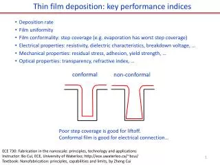
Cycle performance of Si-based Thin Film Anodes for Li-ion Batteries. Kwan-Soo Lee, Jae-Bum Kim, Bong-Suk Jun and Sung-Man Lee Kangwon Nat’l Univ., Chunchon, Korea. 1983. 1992. 1993. 1995. 2002. 1998. Year. Sn, Si SnO, SnO 2 Sn 3 N 4 , Zn 3 N 2. Silicide Sn Alloy.

E N D
Cycle performance of Si-based Thin Film Anodes for Li-ion Batteries Kwan-Soo Lee, Jae-Bum Kim, Bong-Suk Jun and Sung-Man Lee Kangwon Nat’l Univ., Chunchon, Korea
1983 1992 1993 1995 2002 1998 Year Sn, Si SnO, SnO2 Sn3N4, Zn3N2 Silicide Sn Alloy Negative electrode Li SiTON Negative Electrodes for Thin Film Microbattery Li metal Oxide or Nitride Low melting point (181℃) Formation of Li2O or Li3N Very strong reactivity with moisture Irreversible capacity loss at the 1st cycle Limits application area Si : Candidate material High capacity (~4000mAh/g) Little reactivity with air (respectively Li) Little irreversible capacity Very large volume expansion during cycling
Substrate effect Adhesion layer effect Deposition condition effect The variation of thin film deposition condition Morphology Insertion of adhesion layer • Without negative d.c. bias • With negative d.c. bias • Chemically-etched Cu foil • Flat-Cu foil • Zr-deposited Cu foil • Bare-Cu foil Objectives Adhesion effect between substrate and deposited thin film on the cycle properties of Si-based thin-film electrode
Experimental process • Substrate : Ni, Cu foil ( 12 mm dia. ) • Substrate rotation : 13 ~ 14 rpm. • Targets : Si ( 2 in. ) • Deposition Conditions : - Sputtering method - Base pressure : 2 10-6 Torr - Working pressure : 5 10-3 Torr ( Ar ) - Negative DC bias ( - 100 V ) Thin Film Deposition • Substrate : Cu foil ( 12 mm dia. ) • Etchant : A Solution ( FeCl3 + HCl + H2O ), B Solution ( HNO3 + H2O ) Substrate etching • Structure analysis - XRD ( X-ray diffraction ) • Surface roughness analysis - AFM ( Atomic Force Microscope ) • Surface morphology observation - FESEM ( Field-Emission Scanning Electron Mocroscopy ) - SEM ( Scanning Electron Mocroscopy ) • Electrochemical analysis - CR2016 Coin Cells - Counter Electrode : Li metal - Electrolyte : 1 M LiPF6 dissolved in EC/DEC(1:1 Vol) Characterization
Bias effect : Morphology FESEM Images AFM Images (a) (b) (a) Img. RMS : 0.860 nm (b) (a) (b) Img. RMS : 0.188 nm (a) No Bias (b) Bias applied (-100 V) Substrate : Si-wafer
Bias effect : Electrochemical properties The 1st and 2nd cycle Discharge/charge curves EDAX mapping After 1st cycle discharge/charge (a) (b) (a) No Bias (b) Bias applied (-100 V)
Bias effect : Surface morphology EDAX mapping Cycle performance After 10 cycles (a) (b) (a) No Bias (b) Bias applied (-100 V)
Substrate morphology effect : Surface Morphology FESEM Images (Substrate) (a) (b) (c) (a) Cu foil (raw) (b) Cu foil (etched with A solution) (c) Cu foil (etched with B solution ) A Solution : FeCl3 + HCl + H2O B Solution : HNO3 + H2O
Substrate morphology effect : Electrochemical Properties The 1st and 2nd cycle Discharge/charge curves Cycle performance (a) Cu foil (raw) (b) Cu foil (etched with A solution) (c) Cu foil (etched with B solution )
Substrate morphology effect : Surface Morphology FESEM Images After 18 cycles (a) (b) (c) (a) Cu foil (raw) (b) Cu foil (etched with A solution) (c) Cu foil (etched with B solution )
Adhesion layer effect : Electrochemical Properties Cycle performance Cu foil (raw) Cu foil (etched with A solution) Cu foil (etched with B solution ) (a) Cu / Zr / Si (b) Cu / Si
Adhesion layer effect : Surface Morphology FESEM Images After 18 cycles Cu foil (raw) Cu foil (etched with A solution) Cu foil (etched with B solution ) (a) (a) (a) (b) (b) (b) (a) Cu / Zr / Si (b) Cu / Si
Adhesion layer effect : Cross-sectional images SEM Images EDAX mapping After 18 cycles After 18 cycles Reverse & Schematic diagram
Conclusions The cyclability of Si thin film anode can be improved by applying negative d.c bias and adhesion property between substrate and deposited thin film anode is enhanced. The variation of substrate morphology has an effect on the cyclability of Si thin film anodes. For Si thin film anodes, electrochemical cycling performance is improved with the addition of Zr adhesion layer.