Download
1 / 26
260 likes | 442 Views
Nanofabrication and Devices (in ECE and ME Departments). John Melngailis Department of Electrical and Computer Engineering & Institute for Research in Engineering and Applied Physics. University of Maryland, College Park. Nanofabrication.

E N D
Nanofabrication and Devices(in ECE and ME Departments) John Melngailis Department of Electrical and Computer Engineering & Institute for Research in Engineering and Applied Physics. University of Maryland, College Park
Nanofabrication • electron beam lithography, (SEM with beam writing software, 20nm min. features) C.H. Yang • focused ion beam, milling, induced deposition, etching, and implantation, 5-10 nm minimum beam diameter, ~30nm features milled. K. Edinger, A. Stanishevsky, J. Orloff and J. Melngailis • deep reactive ion beam etching, D. DeVoe • aligner/bonder, R. Ghodssi • new Engineering & Applied Sciences Bldg. (6000 sq. ft. class 1000, clean room), ready May,04
Clean room floor plan 6000sq. ft. Class 1000 Space
FIB facilities FEI-620 30 kV Dual-Beam SEM/FIB with Ga+ ion source Micrion FIB-2500 system with 50 kV Ga+ source and 5nm minimum beam diameter Nanofab 150 kV FIB system with alloy ion sources used for implantation of semiconductor devices
Patterned CVD diamond microcrystal A. Stanishevsky, Univ. of Maryland Trenches focused-ion-beam milled in a diamond film. 30nm wide, 600nm deep FIB patterning of diamond films
Focused Ion Beam Milled Cross Section of Part of an Integrated Circuit
FIB/SEM fabricated Nano-ProbesKlaus Edinger LIBRA Ion Beam Shaving Focused Ion Beam Milling Electrochemical probe SNOM probe Scanning Gas-Nozzle “Nano-jet” Electron Beam Induced Deposition Focused Ion Beam Implantation Scanning Thermal Probe AFM / MFM Probe Scanning Electric Field Probe
Nanodevices-Electronic & optical • quantum (C. H. Yang, et. al.) • modeling: nanoMOSFET’s, carbon nanotubes (N. Goldsman & G. Pennington) • magnetic storage (R. Gomez, et al.) • FIB implanted JFET (A. DeMarco & J. Melngailis) • single photon tunneling (I. Smolyaninov & C. Davis)
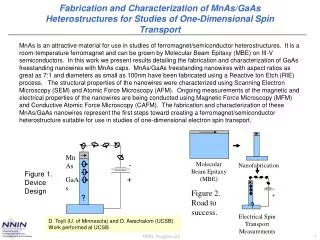
W L le Nanoelectronics Research C.H. Yanga, M.J. Yangb, Andy Chenga, Philip Changa, and J.C. Culbertsonb aDepartment of Electrical and Computer Engineering,University of Maryland, College Park, Maryland bNaval Research Laboratory, Washington DC Fabricated 30 nm conducting InAs wires by (I) MBE growth of heterojunctions, (II) electron beam lithography and (III) wet etching Observed: 1D pure metal regime: W < le < l Ballistic regime: L < le < l l
Nanoelectronics Research C.H. Yanga, M.J. Yangb, Andy Chenga, Philip Changa, and J.C. Culbertsonb aDepartment of Electrical and Computer Engineering,University of Maryland, College Park, Maryland bNaval Research Laboratory, Washington DC Fabricated 100 nm diameter conducting InAs ring, and observed quantum interference due to wave-like electron transport. Left: AFM topography Below: Magnetoresistance
Numerical Boltzmann/Schrodinger Equations: CAD of Quantum Effects in Nanoscale SemiconductorsNeil Goldsman, ECE Dept. UMCP .. Flow Chart Band Diagram Dispersion Relation of QM Well Quantum Domain
Numerical Boltzmann/Schrodinger Equations: CAD of Quantum Effects in Nanoscale SemiconductorsNeil Goldsman, ECE Dept. UMCP Numerical .. SubthresholdCharacteristics I-V Charactistics Current Vector(SHBTE) Current Vector(QM-SHBTE)
Design and Theory of Carbon Nanotube Diodes -V by Gary Pennington and Neil Goldsman ECE Department University of Maryland • Results: Using the tube diameter dependence of the effective mass, band offset, dielectric constant, and hole concentration for an array of Y-junction multiwalled carbon nanotubes, we determined an theoretical analytical formula the junction current as a function of constituent tube diameters. Array of Y-junction carbon nanotubes Experiment: C. Papadopoulos et al., Phys. Rev. Lett 85, 3476 (2000).
Demonstration of current-induced domain wall motion for novel magnetic device applications Mechanism: s-d exchange interaction Ballistic Nanocontact Magnetic Random Access Memory R.D. Gomez, Department of Electrical and Computer Engineering R.D. Gomez, et al., Laboratory for Physical Sciences, College Park MD and University of Maryland, College Park, MD
Demonstration of Fabrication and Characterization of Single Domain Magnet Arrays Topography of interacting NiFe island arrays Ballistic Nanocontact Magnetic Random Access Memory R.D. Gomez, Department of Electrical and Computer Engineering
Single-Photon Tunneling I.I. Smolyaninov, C.Davis et.al. ECE Dept.
Small smart systems &MEMS • Don Devoe- mechanical resonators… • Reza Ghodssi- III-V MEMS, MEMS_VLSI integration • Elisabeth Smela- polymer mEMS
piezo High-Q Piezoelectric Nanomechanical Filter Arrays • Functional filter banks based on nano-scale piezoelectric NEMS structures: • orders-of-magnitude size reduction compared to SAW devices • direct integration with VLSI (ZnO) and high-speed electronics (AlAs) • low power operation • Applications in miniature RF communications, spectrum analyzers, etc.
beam length Piezo (AlAs, ZnO) L=200nm L=30nm gap=L/10 gap=20nm Capacitive (poly-Si) f=60MHz f=3GHz Piezoelectric resonator scaling
Mechanical & thermal devices • Hugh Bruck - funcionally graded materials • Klaus Edinger - scanning thermal nanoprobe
400 oC T t Functionally Graded Smart Thin Film 1 mm 5 mm Mf >Troom Ms <Troom Functionally Graded Smart Thin Film Out-of-plane Displacement Infrared Temperature Field ATC 1200 SPUTTERING MACHINE Microdevice Performance Characterization Hugh Bruck ME Dept “Micropump” “Microbubble” Fabrication of Functionally Graded Thin Films Force Modulation Microscopy Atomic Force Microscopy Nano Indenter XP 1 mm Dimension 3000 SPM Nanoscale Material Property and Stress Characterization Film-substrate interface After Actuation Before Actuation s = 100 MPa z T = 44 oC Finite Element Analysis Digital Image Correlation Ms = 43 oC, Mf = 23 oC U-DISPLACEMENT V-DISPLACEMENT 100 nm 100 nm 150 nm 150 nm r Ms = 3 oC, Mf = -17 oC Nanoscale Structure and Deformation Characterization Microscale Modeling of Device Performance
Scanning Thermal Probe Klaus Edinger LIBRA Me3 MeCp Pt precursor deposits a Pt/carbon mixture Filament diameter ~ 30 nmTip end radius < 20 nm Height: 2-5 m
Nanofabricated Scanning Thermal ProbeKlaus Edinger, LIBRA LIBRA • Passive mode: the resistance of the wire in contact with the sample is measured, using a low current temperature mapping • Active mode: the wire is heated by applied an AC-current mapping of thermal conductivity and diffusivity. • Free-standing 20-50 nm Pt “wire” grown by electron beam induced deposition from an organometallic precursor gas on an AFM type cantilever. • Low thermal mass; high sensitivity; high spatial resolution Topographic image (left): Only the metal leads are visible. The two buried resistors are indicated by the dotted line.Temperature image (right): The two buried resistors (heating current ~2mA) are visible.
Summary • nanofabrication capabilities (e-beam/SEM, focused ion beam, MEMS, new EAS Building with clean room) • nanodevices: electrical & optical • nanoMEMS • mechanical and thermal devices