Download
1 / 32
320 likes | 439 Views
Drift Chamber System • hardware status Run 2007 • shutdown activities 2008 . Malte Hildebrandt. MEG Review Meeting, 20th Feb 2008. Installation 2007. • main changes / improvements compared to installation in 2006:

E N D
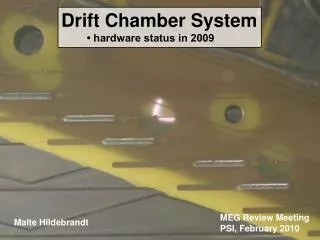
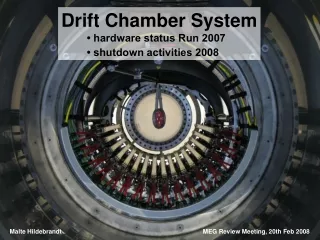
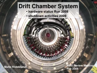
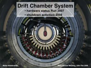
Drift Chamber System • hardware status Run 2007 • shutdown activities 2008 Malte Hildebrandt MEG Review Meeting, 20th Feb 2008 Malte Hildebrandt MEG Review Meeting, 20.02.2008
Installation 2007 • main changes/improvements compared to installation in 2006: • modifications of support structure ↔ clearance to N2 bag • new design of gas manifolds ↔ less influence on e+ trajectory • placed at larger lzl- and larger r- coordinate • different material (0.5mm Al → 1mm PVC) • 16/16 drift chamber modules • as in 2006: each dc module tested in test setup „aquarium“ (He/C2H6 inside module and Helium outside module) • cosmics run in lab, modules mounted in support structure → sort out cable mismatch „inside COBRA“ Malte Hildebrandt MEG Review Meeting, 20.02.2008
Drift Chamber System dc support flange to BTS „MEG“ target dc15 dc00 gas manifold ds Malte Hildebrandt MEG Review Meeting, 20.02.2008
Alignment – Part1 • measurement of identification marks wrt reference bolts (3D touch-sensitive sensor in mechanical workshop) identification mark identification mark reference bolt „connection“ to position of • anode wires and • cathode pattern (x-y-measuring table in lab) reference bolt Malte Hildebrandt MEG Review Meeting, 20.02.2008
Alignment – Part2 • surveying of identification marks wrt support structure and beam axis ( survey with theodolite by survey group) reference holes in support structure → 2 vectors: • connecting line of adjacent holes • middle of connecting line to identification mark (chamber plane) identification marks on dc module Malte Hildebrandt MEG Review Meeting, 20.02.2008
Chamber Shift • observation after measurement and survey: • shift of modules • tilt of modules → ChamberShift in data base • corrections in x, y, z up to 2mm • corrections along vector of chamber plane up to 6mrad upstream displacement x50 downstream displacement x50 Malte Hildebrandt MEG Review Meeting, 20.02.2008
Wire Displacement • deviation(wire#) in R and Z of expected hit point to fitted track (including ChamberShift data) → measure of wire displacement before alignment procedure → after 3 iterations: <0.01cm tilt shift • mechanical deformation of dc module/support structure ? → survey dc + target system before installation („hanging“) → survey after installation in COBRA („sitting“ ) Malte Hildebrandt MEG Review Meeting, 20.02.2008
Survey of Target • observation after dc installation (Aug. 2007): target slightly misaligned → „survey“ with vertical and horizontal laser projections → photos with digital camera and geometrical analysis (PRK) → numbers are included in MC Malte Hildebrandt MEG Review Meeting, 20.02.2008
Target Malte Hildebrandt MEG Review Meeting, 20.02.2008
Survey of Target • observation after dc installation (Aug. 2007): target slightly misaligned → „survey“ with vertical and horizontal laser projections → photos with digital camera and geometrical analysis (PRK) → numbers are included in MC • before dismounting dc system (Jan. 2008): → photogrammetric survey by survey group (no time for theodolite survey) • several photos from different positions (~1h) • analysis later with special software and camera calibration • but: maybe problems due to small angles and glancing intersections Malte Hildebrandt MEG Review Meeting, 20.02.2008
Photogrammetric Survey of Target reference points ruler (absolute scale) Malte Hildebrandt MEG Review Meeting, 20.02.2008
Survey of Target • observation after dc installation (Aug. 2007): target slightly misaligned → „survey“ with vertical + horizontal laser projections → photos with digital camera, geometrical analysis (PRK) → numbers are included in MC • before dismounting dc system (Jan. 2008): → photogrammetric survey by survey group (no time for theodolite survey) • several photos from different positions (~1h) • analysis later with special software and camera calibration • but: maybe problems due to small angles and glancing intersections before Run 2008: • identification marks on target/frame • schedule theodolite survey of dc + target (~1d) Malte Hildebrandt MEG Review Meeting, 20.02.2008
Drift Chamber Operation • startup/de-bugging phase (noise, HV & SlowControl vs magnetic field) • Cosmic Ray Run 11.-17.10.2007 (1.2M events) • z-calibration • wire positioning, alignment • gain calibration • standalone Michel Run (08.-14.11.2007) → ultra low (3M + 2M events) • xt -calibration • Michel spectrum → low (2 M events) • confirm stable dc operation at „normal“ beam intensity • tune tracking algorithm • MEG Run Malte Hildebrandt MEG Review Meeting, 20.02.2008
Drift Chamber Operation • startup/de-bugging phase (noise, HV & SlowControl vs magnetic field) • Cosmic Ray Run 11.-17.10.2007 (1.2M events) • z-calibration • wire positioning, alignment • gain calibration • standalone Michel Run (08.-14.11.2007) → ultra low (3M + 2M events) • xt -calibration • Michel spectrum → normal (2 M events) • confirm stable dc operation at „normal“ beam intensity • tune tracking algorithm • MEG Run Malte Hildebrandt MEG Review Meeting, 20.02.2008
open DS endcap Jan 2008 disconnected patchpanel inside Disconnected Cables • missing LV dc6u • missing signal channels 1anode wire = signals from both sides (out of 288) 3 anode signals = signal from one side (out of 576) 23 cathode / hood signals (out of 1152) (only one cell with 2 missing cathode signals) Remark: everything fine during startup, most likely explanation for mishap: • LV cables: stiff and rigid • signal cables: slippery → slight mechanical tension → very slow movement, even we fixed with tape and cable ties → finally connector slips out of socket → improved strain-relief of cables on pcb (design finished, parts under construction) → additional test after inserting dc support structure, before closing endcap Malte Hildebrandt MEG Review Meeting, 20.02.2008
O2 O2 O2 O2 O2 O2 Sensors US endcap DS endcap He_in He_in dc He_out He_out • Alphasens O2 sensors : • metal/air battery: I proportional O2 concentration → calibration with 20.8% O2 → U0 = R·I0 → “aging”: exposed to 20.8% O2 → I0 = I0(t) • powerfull tool to monitor Helium concentration inside COBRA and to „identify“ leaks Malte Hildebrandt MEG Review Meeting, 20.02.2008
o u t s i d e ? → recent activities (since beginning of January): • dc support structure moved out of COBRA • test setup „aquarium“ installed and operational in pE5 • „weakest“ dc module dismounted → optical inspection suspicious spot: sealing of HV connection to pcb DC HV Problems • 6 dc modules showed frequent HV trips (1850V) when cHe_COBRA >97% MC: influence on • m stopping distribution and • reconstructed momentum resolution of e+ → decission: air admixture to „adjust“ 95% < cHe_COBRA< 97% • but: due to trips slight deterioration during run… → situation end of run: 16 / 32 planes operated at 1850V 11 / 32 planes operated at 1800V 5 / 32 planes not operational (<1700V) Malte Hildebrandt MEG Review Meeting, 20.02.2008
HV Connection hood readout hood Vernier pattern anode decoupling capacitors pre-amplifier cards HV connection to pcb Malte Hildebrandt MEG Review Meeting, 20.02.2008
Anode PCB Malte Hildebrandt MEG Review Meeting, 20.02.2008
next steps: • all dc modules with planes labled „not operational“: • dismount from support structure → optical inspection • redo sealing of HV connection • confirm HV stability in test setup „aquarium“ Next Steps • 1st test with „weakest“ dc module in „aquarium“: HV trip reproduced → new sealing → stable operation with 1875V at 99.7% Helium in „aquarium“ (O2-sensor) → depending on success of these activities: • all dc modules with planes operated at1800V: • dismount from support structure • check/redo sealing (• confirm HV stability in aquarium) • no activities scheduled for planes operated at 1850V Malte Hildebrandt MEG Review Meeting, 20.02.2008
Current vs Beam Rate • two different settings for m stopping rate : ultra low: 5.0·106m/s normal : 3.1·107m/s Ianode [nA] dc4A m stop rate [Hz] Malte Hildebrandt MEG Review Meeting, 20.02.2008
Current vs HV • normal m stopping rate 3.1·107m/s • HV scan from 1600V to 1850V → Ianode shows exponential relation as a function of HV! but: slight saturation visible • only ~10V voltage drop due to 1M resistor and 10mA → saturation due to high gain and space charge effects? → analysis of pulse heigth or charge distribution ln(Ianode) dc4A, low rate HV [V] Malte Hildebrandt MEG Review Meeting, 20.02.2008
Wire Hit Rates cut condition for charge : > 0.6 V·ns → why is 1st cell of plane A and plane B much higher than expected ? → why is 1st cell of plane A higher than 1st cell of plane B ? normal rate, dc08 data • MC H.Nishigushi Malte Hildebrandt MEG Review Meeting, 20.02.2008
Drift Lines from Track potential wire (GND) anode wire B B A A Malte Hildebrandt MEG Review Meeting, 20.02.2008
Drift Lines from Track potential wire (GND) anode wire B B A A Malte Hildebrandt MEG Review Meeting, 20.02.2008
Drift Lines from Track potential wire (GND) anode wire B B A A Malte Hildebrandt MEG Review Meeting, 20.02.2008
Drift Lines from Track potential wire (GND) anode wire B B A A Malte Hildebrandt MEG Review Meeting, 20.02.2008
MC + Data → after implementation of „cell 0 geometry“ in MC: cut condition for charge : > 0.6 V·ns normal rate, dc08 data • MC H.Nishigushi → still some work to do understand further discrepancies Malte Hildebrandt MEG Review Meeting, 20.02.2008
Charge Distribution run 6092, 6093, low rate wire 1 wire 2 wire 0 wire 3 wire 4 wire 5 wire 6 wire 7 wire 8 H.Nishigushi Malte Hildebrandt MEG Review Meeting, 20.02.2008
data: •S(single wire hite rates) too large due to contributions of small pulses on wire 0 • estimation of correction factor 0.9 (Ch.Topchyan): → gas gain ~4.4·105 @ 1850V What is the reason for the small pulses? • low collection efficiency? • GARFIELD • attachment / recombination ? • data analysis Current, Gas Gain • dE/dX, r → energy deposition along track w-value → primary ionisation along track track length → primary ionisation per traversing particle rate, surface → Iprimary ionisation Iprimary ionisation x gas gain = Imeasured • accumulated charge (innermost anode wire): ~1C/cm/8months → monitor chamber parameters Malte Hildebrandt MEG Review Meeting, 20.02.2008
PSI Savety • dc gas system: • fire protected cabinet with ventillation system to operate 50l bottle ethane • pE5 gas warning system: • in total 8 sensors: 3 sensors for O2 4 sensors for C2H6 1 sensor for H2 Malte Hildebrandt MEG Review Meeting, 20.02.2008
Conclusion • dc hardware problems have huge impact on overall performance of dc system → exchange / repair broken pre-amplifier cards → improve strain-relief of LV and signal cables → repair bad potting of HV connection on dc modules to ensure HV stability in pure Helium environment → in parallel: construction of 2nd spare module (dc18) remark: dc17 available in laboratory (completely tested) Malte Hildebrandt MEG Review Meeting, 20.02.2008