Download

1 / 25
280 likes | 533 Views
Digital Transmission through the AWGN Channel. ECE460 Spring, 2012. Geometric Representation. Orthogonal Basis Orthogonalization (Gram-Schmidt) Pulse Amplitude Modulation Baseband Bandpass Geometric Representation 2-D Signals Baseband Bandpass

E N D
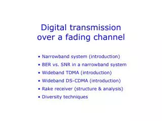
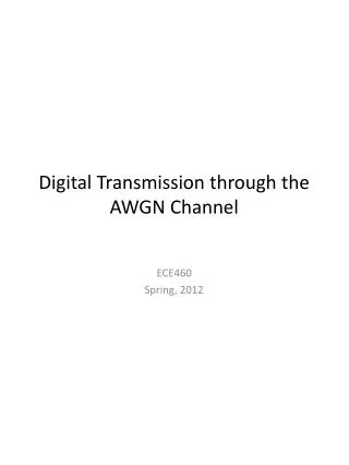
Digital Transmission through the AWGN Channel ECE460 Spring, 2012
Geometric Representation • Orthogonal Basis • Orthogonalization (Gram-Schmidt) • Pulse Amplitude Modulation • Baseband • Bandpass • Geometric Representation • 2-D Signals • Baseband • Bandpass • Carrier Phase Modulation (All have same energy) • Phase-Shift Keying • Two Quadrature Carriers • Quadrature Amplitude Modulation • Multidimensional • Orthogonal • Baseband • Bandpass • Biorthogonal • Baseband • Bandpass
Geometric Representation • Gram-Schmidt Orthogonalization • Begin with first waveform, s1(t) with energy ξ1: • Second waveform • Determine projection, c21, onto ψ1 • Subtract projection from s2(t) • Normalize • Repeat
Pulse Amplitude ModulationBaseband Signals • Binary PAM • Bit 1 – Amplitude + A • Bit 0 – Amplitude - A • M-ary PAM M-ary PAM Binary PAM
Pulse Amplitude ModulationBandpass Signals • What type of Amplitude Modulation signal does this appear to be? X
PAM SignalsGeometric Representation • M-ary PAM waveforms are one-dimensional • where d = Euclidean distance between two points d d d d d 0
Optimum Receivers • Start with the transmission of any one of the M-ary signal waveforms: • Demodulators • Correlation-Type • Matched-Filter-Type • Optimum Detector • Special Cases (Demodulation and Detection) • Carrier-Amplitude Modulated Signals • Carrier-Phase Modulation Signals • Quadrature Amplitude Modulated Signals • Frequency-Modulated Signals Demodulator Detector Output Decision Sampler
DemodulatorsCorrelation-Type Next, obtain the joint conditional PDF
DemodulatorsMatched-Filter Type • Instead of using a bank of correlators to generate {rk}, use a bank of N linear filters. • The Matched Filter Key Property: if a signal s(t) is corruptedby AGWN, the filter with impulse response matched to s(t) maximizes the output SNR Demodulator
Optimum Detector • Maximum a Posterior Probabilities (MAP) • If equal a priori probabilities, i.e., for all M and the denominator is a constant for all M, this reduces to maximizing called maximum-likelihood (ML) criterion.
Probability of ErrorBinary PAM Baseband Signals • Consider binary PAM baseband signalswhere is an arbitrary pulse which is nonzero in the interval and zero elsewhere. This can be pictured geometrically as • Assumption: signals are equally likely and that s1 was transmitted. Then the received signal is • Decision Rule: • The two conditional PDFs for r are 0
Example 7.5.3 • Consider the case of binary PAM signals in which two possible signal points are where is the energy per bit. The prior probabilities are Determine the metrics for the optimum MAP detector when the transmitted signal is corrupted with AWGN.
Probability of ErrorM-ary PAM Baseband Signals • Recall baseband M-ary PAM are geometrically represented in 1-D with signal point values of • And, for symmetric signals about the origin, • where the distance between adjacent signal points is . • Each signal has a different energies. The average is
Demodulation and DetectionCarrier-Amplitude Modulated Signals • Demodulation of bandpass digital PAM signal • Transmitted Signal: • Received Signal: • Crosscorrelation • Optimum Detector Received Signal r(t) Oscillator
Two-Dimensional Signal Waveforms • Baseband Signals • Are these orthogonal? • Calculate ξ. • Find basis functions of (b).
Problem 7.22 • In an additive white Gaussian noise channel with noise power-spectral density of , two equiprobable messages are transmitted by • Determine the structure of the optimal receiver • Determine the probability of error.
Two-Dimensional Bandpass Signals • Carrier-Phase Modulation • Given M-two-dimensional signal waveforms • Constrain bandpass waveforms to have same energy
Demodulation and DetectionCarrier-Phase Modulated Signals • The received signal: • Giving basis vectors as • Outputs of correlators:
Two-Dimensional Bandpass Signals • Quadrature Amplitude Modulation
Multidimensional Signal WaveformsOrthogonal • Multidimensional means multiple basis vectors • Baseband Signals • Overlapping(Hadamard Sequence) • Non-Overlapping • Pulse Position Mod.(PPM)
Multidimensional Signal WaveformsOrthogonal • Bandpass Signals • As before, we can create bandpass signals by simply multiplying a baseband signal by a sinusoid: • Carrier-frequency modulation: Frequency-Shift Keying (FSK)
Multidimensional Signal WaveformsBiorthogonal • Baseband • Begin with M/2 orthogonal vectors in N = M/2 dimensions. • Then append their negatives • Bandpass • As before, multiply the baseband signals by a sinusoid.
Multidimensional Signal WaveformsSimplex • Subtract the average of M orthogonal waveforms • In geometric form (e.g., vector) • Where the mean-signal vector is • Has the effect of moving the origin to reducing the energy per symbol
Demodulation and DetectionCarrier-Amplitude Modulated Signals • Demodulation of bandpass digital PAM signal • Transmitted Signal: • Received Signal: • Crosscorrelation • Optimum Detector Received Signal r(t) Oscillator