Download
1 / 29
290 likes | 478 Views
Digital transmission over a fading channel. Narrowband system (introduction) Wideband TDMA (introduction) Wideband DS-CDMA (introduction) Rake receiver (structure & analysis). Three kinds of systems (1). Narrowband system:.

E N D
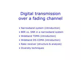
Digital transmission over a fading channel • Narrowband system (introduction) • Wideband TDMA (introduction) • Wideband DS-CDMA (introduction) • Rake receiver (structure & analysis)
Three kinds of systems (1) Narrowband system: Flat fading channel, single-tap channel model, performance enhancement through diversity (future lecture). System bandwidth Tm = delay spread of multipath channel bit or symbol T = bit or symbol duration
No intersymbol interference (ISI) Narrowband system: Adjacent symbols (bits) do not affect the decision process (in other words there is no intersymbol interference). Received replicas of same symbol overlap in multipath channel No intersymbol interference at decision time instant However: Fading (destructive interference) is still possible
Decision circuit In the binary case, the decision circuit compares the received signal with a threshold at specific time instants (usually somewhere in the middle of each bit period): Noisy and distorted symbols “Clean” symbols Decision circuit Decision threshold Decision time instant
Three kinds of systems (2) Wideband system (TDM, TDMA): Selective fading channel, transversal filter channel model, good performance possible through adaptive equalization (future lecture). Intersymbol interference causes signal distortion Tm = delay spread of multipath channel T = bit or symbol duration
Receiver structure The intersymbol interference of received symbols (bits) must be removed before decision making (the case is illustrated below for a binary signal, where symbol = bit): Symbols with ISI Symbols with ISI removed “Clean” symbols Adaptive equalizer Decision circuit Decision time instant Decision threshold
Three kinds of systems: BER performance Frequency-selective channel (with equalization) BER Frequency-selective channel (no equalization) “BER floor” AWGN channel (no fading) Flat fading channel S/N
Three kinds of systems (3) Wideband system (DS-CDMA): Selective fading channel, transversal filter channel model, good performance possible through use of Rake receiver (this lecture). Tm = delay spread of multipath channel Tc = Chip duration ... Bit (or symbol) T = bit (or symbol) duration
Rake receiver structure and operation Rake receiver <=> a signal processing example that illustrates some important concepts Rake receiver is used in DS-CDMA (Direct Sequence Code Division Multiple Access) systems Rake “fingers” synchronize to signal components that are received via a wideband multipath channel Important task of Rake receiver is channel estimation Output signals from Rake fingers are combined, for instance using Maximum Ratio Combining (MRC)
To start with: multipath channel Suppose a signal s(t) is transmitted. A multipath channel with M physical paths can be presented (in equivalent low-pass signal domain) in form of its Channel Impulse Response (CIR) in which case the received (equivalent low-pass) signal is of the form .
Sampled channel impulse response Sampled Channel Impulse Response (CIR) The CIR can also be presented in sampled form using N complex-valued samples uniformly spaced at most 1/W apart, where W is the RF system bandwidth: Uniformly spaced channel samples Delay () CIR sampling rate = for instance sampling rate used in receiver during A/D conversion.
Rake finger selection Channel estimation circuit of Rake receiver selects Lstrongest samples (components) to be processed in L Rake fingers: Only one sample chosen, since adjacent samples may be correlated Only these samples are constructively utilized in Rake fingers Delay () In the Rake receiver example to follow, we assume L = 3.
Received multipath signal Received signal consists of a sum of delayed (and weighted) replicas of transmitted signal. Blue samples indicate signal replicas processed in Rake fingers Green samples only cause interference All signal replicas are contained in received signal Signal replicas: same signal at different delays, with different amplitudes and phases Summation in channel <=> “smeared” end result :
Rake receiver (Generic structure, assuming 3 fingers) Received baseband multipath signal (in ELP signal domain) Channel estimation Weighting Finger 1 Output signal (to decision circuit) Finger 2 Finger 3 Rake receiver Path combining
Channel estimation Channel estimation A C B A Amplitude, phase and delay of signal components detected in Rake fingers must be estimated. B Each Rake finger requires delay (and often also phase) information of the signal component it is processing. C Maximum Ratio Combining (MRC) requires amplitude (and phase if this is not utilized in Rake fingers) of components processed in Rake fingers.
Rake finger processing Case 1: same code in I and Q branches - for purpose of easy demonstration only - no phase synchronization in Rake fingers Case 2: different codes in I and Q branches - the real case e.g. in IS-95 and WCDMA - phase synchronization in Rake fingers
Rake finger processing (Case 1: same code in I and Q branches) Received signal Stored code sequence I branch To MRC Delay I/Q Q branch Output of finger: a complex signal value for each detected bit
Correlation vs. matched filtering Basic idea of correlation: Stored code sequence Received code sequence Same end result (in theory) Same result through matched filtering and sampling: Received code sequence Matched filter Sampling at t = T
Rake finger processing Correlation with stored code sequence has different impact on different parts of the received signal = desired signal component detected in i:th Rake finger = other signal components causing interference = other codes causing interference (+ noise ... )
Rake finger processing Illustration of correlation (in one quadrature branch) with desired signal component (i.e. correctly aligned code sequence) “1” bit “0” bit “0” bit Desired component Stored sequence After multiplication Strong positive/negative “correlation result” after integration
Rake finger processing Illustration of correlation (in one quadrature branch) with some other signal component (i.e. non-aligned code sequence) “1” bit “0” bit Other component Stored sequence After multiplication Weak “correlation result” after integration
Rake finger processing Mathematically: Correlation result for bit between Desired signal Interference from same signal Interference from other signals
Rake finger processing Set of codes must have both: - good autocorrelation properties (same code sequence) - good cross-correlation properties (different sequences) Large Small Small
Rake finger processing (Case 2: different codes in I and Q branches) Stored I code sequence Received signal To MRC for I signal Delay I/Q I branch To MRC for Q signal Q branch Required: phase synchronization Stored Q code sequence
Phase synchronization When different codes are used in the quadrature branches (as in practical systems such as IS-95 or WCDMA), phase synchronization is necessary. I/Q Phase synchronization is based on information within received signal (pilot signal or pilot channel). Note: phase synchronization must be done for each finger separately! Pilot signal Q Signal in Q-branch I Signal in I-branch
Weighting (Case 1: same code in I and Q branches) Maximum Ratio Combining (MRC) means weighting each Rake finger output with a complex number after which the weighted components are summed “on the real axis”: Component is weighted Phase is aligned Rake finger output is complex-valued Instead of phase alignment: take absolute value of finger outputs ... real-valued
Phase alignment The complex-valued Rake finger outputs are phase-aligned using the following simple operation: Before phase alignment: Phasors representing complex-valued Rake finger outputs After phase alignment:
Maximum Ratio Combining (Case 1: same code in I and Q branches) The signal value after Maximum Ratio Combining is: The idea of MRC: strong signal components are given more weight than weak signal components. Why is the performance of MRC better than that of Equal Gain Combining (EGC)? The answer will be given in future lecture (diversity methods).
Maximum Ratio Combining (Case 2: different codes in I and Q branches) Output signals from the Rake fingers are already phase aligned (this is a benefit of finger-wise phase synchronization). Consequently, I and Q outputs are fed via separate MRC circuits to the decision circuit (e.g. QPSK demodulator). MRC I Finger 1 I Q Quaternary decision circuit I Finger 2 Q MRC Q :