Download
1 / 9
90 likes | 223 Views
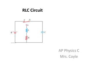
Series RLC Circuit PHY 213 and PHY 201. Important points to consider: Sketch the phasor (vector) diagram A circuit will appear, to the power supply, inductive if X L > X C or capacitive if X C > X L Use subscripts. L. R. C. The Problem:

E N D
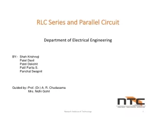
Series RLC CircuitPHY 213 and PHY 201 Important points to consider: • Sketch the phasor (vector) diagram • A circuit will appear, to the power supply, inductive if XL > XC or capacitive if XC > XL • Use subscripts
L R C • The Problem: • A series ac circuit driven by a 120 V, 60.0 Hz supply consists of the following components. Solve for all unknowns. • R = 1500 • L = 2.12 H • C = 2.00 F
+ y + y XL R R X + x + x XC Z
+ y + y XL R R X + x XC + x Z • X is capacitive because XC > XL.
Solving the triangle: -19.5 degrees is the phase angle between the current in the circuit and the potential difference (voltage) applied to the circuit.
Of special interest is the fact that the sum of the voltages is greater than the applied voltage.
This is because these are RMS voltages and not instantaneous voltages. That is, these voltages do not occur at the same time. Consider the graph below. It represents the RMS voltages across the three components in a series RLC circuit. If we consider the individual RMS voltages at the time represented by the black vertical line, we will see that these RMS voltages sum to 120 V. Note that the peak voltage will be 170 V.
Apparent power is the power “apparently” consumed by the circuit. That is, current times voltage with no regard to reactance. However, “real” power is always the power consumed by the resistance. This is the power that we pay for on our electric bill.
Power factor gives us an indication of the amount of reactive current flowing in the circuit. Or: