Download
1 / 121
1.21k likes | 1.39k Views
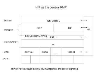
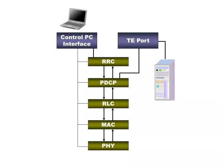
Control PC Interface. TE Port. RRC. PDCP. RLC. MAC. PHY. Control PC Interface. TE Port. CteXXXXX(). 36.331. RRC. 36.323. CpdcpXXXXX(). PDCP. CrlcXXXXX(). RLC. 36.322. 36.321. CmacXXXXX(). MAC. CphyXXXXX(). 36.104,36.211,36.212 36.213,36.214,36.302. PHY. Protocol CT.

E N D
Control PC Interface TE Port RRC PDCP RLC MAC PHY
Control PC Interface TE Port CteXXXXX() 36.331 RRC 36.323 CpdcpXXXXX() PDCP CrlcXXXXX() RLC 36.322 36.321 CmacXXXXX() MAC CphyXXXXX() 36.104,36.211,36.212 36.213,36.214,36.302 PHY
Protocol CT 36.523 RF CT 36.521-1, 36.521-3 23.401,24.301,29.274, 32.426,33.102,33.401, 33.402 NAS 36.331 RRC 36.323 PDCP RLC 36.322 36.321 MAC 36.104,36.211,36.212 36.213,36.214,36.302 PHY
SGSN PCRF HSS MME IP eNodeB SGW (Serving Gateway) PGW (PDN Gateway) UE
MSC Voice Call Traffic Path Registration to CS Network Path BSC BTS (GSM) Paging Path SGSN SGs RNC UE NodeB (UMTS) MME IP eNodeB (LTE) SGW (Serving Gateway) PGW (PDN Gateway)
SGSN PCRF HSS MME IP eNodeB SGW (Serving Gateway) PGW (PDN Gateway) UE EPS Bearer External Bearer
UE Internet EPC E-UTRAN Peer Entity eNodeB S-GW P-GW End-to-End Service EPS Bearer External Bearer E-RAB S5/S8 Bearer Radio Bearer S1 Bearer Gi Radio S1 S5/S8
ON Duration DRX Cycle DRX Cycle PDCCH Reception Here DRX Inactivity Time ON Duration DRX Cycle DRX Cycle
PDCCH Reception Here DRX Inactivity Time ON Duration DRX Cycle DRX Command MAC CE Reception Here (Both DRX Inactivity timer and OnDuration Timer stops here) ON Duration Short DRX Cycle Short DRX Cycle Short DRX Cycle Timer Long DRX Cycle
http://lteworld.org/blog/measurements-lte-e-utran High frequency UE Current Cell Center frequency Low frequency High frequency UE Current Cell Target Cell Center frequency Low frequency
High frequency UE Current Cell Target Cell Center frequency Low frequency Target Cell High frequency UE Current Cell Center frequency Low frequency
High frequency UE Current Cell Target Cell Center frequency Low frequency High frequency UE Current Cell Target Cell Center frequency Low frequency
High frequency UE Current Cell Target Cell Center frequency Low frequency High frequency UE Current Cell Center frequency Target Cell Low frequency
IMS SIP H.323 H.263 RTP etc SMS Voice (VoIP) Video
SIP Application Servers SGSN IMS (CSCF) HSS PCRF MME Other IP Network eNodeB SGW (Serving Gateway) PGW (PDN Gateway) UE
SIP Register Server B A Clients INVITE REGISTER (Contact Address) 100 Trying 180 Ringing AUTHENTICATION REQUEST 200 OK REGISTER Media Transfer (Credentials) OK BYE 200 OK
PC1 – UE PC PC2
Server PC Ethernet Cable TE Port Wireshark RF Port LTE Network Simulator Wireshark UE PC
Dummy Hub IP Network Data Server Router TE Port RF Port LTE Network Simulator Wireshark IP Monitoring PC for troubleshot Wireshark UE PC
Bit Stream Bit Stream I/Q I/Q I/Q 36.211 6.3.1 36.211 6.3.2 36.211 6.3.3 36.211 6.3.4 36.211 6.5
Cell Specific Reference Signal PDCCH PA PB PDSCH : in the same symbol as reference signal PDSCH : in the symbol with no reference signal
In some subframe, there can be no SRS depending on SRS Scheduling parameter settings 1 subframe
Attach Request PDN Connectivity Request PDN type Access point name EPS attach type value Old GUTI or IMSI UE network capability NAS : Security Mode Command Replayed UE security capabilities Attah Accept Activate Default EPS Bearer Setup Request PDN type Access point name GUTI EPS attach result value
SIB1 TAC (Tracking Area Code) Tracking Area Update Request Old GUTI EPS Bearer Context Status Old Location Area Identification Tracking Area Update Accept GUTI TAI List EPS Bearer Context Status Location Area Identification
RRC DedicatedInfoNAS NAS Message(EMM) NAS(ESM) Message Type (8 bits) Message Type (8 bits) Protocol Discriminator + Message Authentication Code + Sequence Number (44 bits) Security Header Type (4 bits) Length of DedicatedInfoNAS C1 (RRC Message Type Identifier : 4 bits)
1 frame 1 subframe 1 slot PUCCH Region Subband 3 Subband 2 Subband 1 Subband 0 PUCCH Region
PUCCH Region Subband 3 Subband 2 Subband 1 Subband 0 PUCCH Region
PUCCH Region Subband 3 Subband 2 Subband 1 Subband 0 PUCCH Region
PUCCH Region Subband 3 Subband 2 Subband 1 Subband 0 PUCCH Region
PUCCH Region Subband 3 Subband 2 Subband 1 Subband 0 PUCCH Region
PUCCH Region Subband 3 Subband 2 Subband 1 Subband 0 PUCCH Region
(b) (a) (c) (d) (e) 1 subframe
LTE WCDMA CDMA Voice Comm Voice Comm CSFB CSFB Packet Comm Packet Comm Packet Comm Packet Comm HO HO HO RD RD RD RD Idle Idle Idle Idle CR CR CR CS CS CS CS Power On CS : Cell Selection CR : Cell Reselection RD : Cell Redirection HO : Handover CSFB : CS Fallback
NW UE RRC Connection Request T300 RRC Connection Setup NW UE RRC Connection Request T300 RRC Connection Reject
UE Higher Layer UE Lower Layer Out of Sync Indication Out of Sync Indication N310 Times Out of Sync Indication In Sync Indication T310 In Sync Indication N311 Times In Sync Indication
UE Higher Layer UE Lower Layer Out of Sync Indication Out of Sync Indication N310 Times Out of Sync Indication T310 Triggering Handover Procedure UE Higher Layer UE Lower Layer Out of Sync Indication Out of Sync Indication N310 Times Out of Sync Indication T310 Initiating Connection Reestablishment
op op op op 1 0 + + + + 0 0 1 0 0 0 ip ip ip ip 0 1 1 0 0 0 0 0 0 0 1 0 1 0 0 0 0 1 -1 -1 -1 -1 -1 -1 -1 -1 op op op op Z Z Z Z Z Z Z Z + + + +
op op op op 0 1 + + + + 1 1 1 0 0 0 ip ip ip ip 0 1 1 0 1 1 0 0 0 0 1 0 1 0 1 1 1 0 -1 -1 -1 -1 -1 -1 -1 -1 op op op op Z Z Z Z Z Z Z Z + + + +
op op op op 0 1 + + + + 0 0 1 0 1 1 ip ip ip ip 0 1 1 0 0 0 1 1 1 1 1 0 1 0 0 0 0 1 -1 -1 -1 -1 -1 -1 -1 -1 op op op op Z Z Z Z Z Z Z Z + + + +
op op op op 1 0 + + + + 1 1 1 0 1 1 ip ip ip ip 0 1 1 0 1 1 1 1 1 1 1 0 1 0 1 1 1 0 -1 -1 -1 -1 -1 -1 -1 -1 op op op op Z Z Z Z Z Z Z Z + + + +
GPS Signal Frame Structure Telemetry and handover words(TLM and HOW) Satellite clock, GPS time relationship Telemetry and handover words(TLM and HOW) Ephemeris(precise satellite orbit) Telemetry and handover words(TLM and HOW) Almanac component (satellite network synopsys, error correction) Word 1-2 3-10 1-2 3-10 1-2 3-10 Subframe 1 2 3 4 5 Frame 300 bits 1500 bits
x(n) y(n) x(n) y(n) x(n) y(n)
Sum of Times (Sum of Multiplication) Correlation Inner Product Discrete Fourier Transform Convolution
FIR IIR
This means the result of convolution is an array (vector) with the size = n This means that each element (each value) of the convolution comes from “Sum of Multiplication” • This is same as g[-m + n] • g[-m + n] is same as g[-(m-n)] • g[-(m-n)] is same as g[-m] shifted by n • g[-m] is the reflection of g[m] around y axis g[-(m-n)] =g[n-m] g[m] g[-m] n