Download
1 / 36
360 likes | 418 Views
Presentation for Development Process Experiment. By: Nir Shahar and Amir Kleinhendler Supervisor: Ina Rivkin. AGENDA. System main features. System block diagrams. I/O Controller. System Controller. Memory. Logic units. Suggestions. . PROJECT OBJECTIVE.

E N D
Presentation for Development Process Experiment • By: Nir Shahar and Amir Kleinhendler • Supervisor: Ina Rivkin
AGENDA • System main features. • System block diagrams. • I/O Controller. • System Controller. • Memory. • Logic units. • Suggestions.
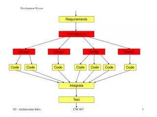
PROJECT OBJECTIVE • The project objective is to create the foundations for an experiment at the high speed digital lab which covers the full design flow. The foundations include the main digital system and the debug environment used to debug the system.
SYSTEM MAIN FEATURES • The complete system will illustrate a full computer with the below parts. • The system is composed of 8 separate units: • Keyboard • LCD display • 8 LEDs • 4 switches • I/O controller • System controller • one simple logic unit • FIFO Memory unit • System functionality: • The computer will receive an OPcode followed by data through PS/2 keyboard. The OPcode and the data will be delivered to an I/O controller and from there to the FIFO memory character by character. • The system controller will read the data from the FIFO memory and then build the parallel OPcode and data. After the building the data will be sent to the logic bus for the use of the logic units. • The correct logic unit will collect the data and then perform the appropriate logic action. • After performing the logic action the result will be send to the I/O controller and from there to the LCD display. • The system has more 4 switches and 8 LEDs to control on the system state.
SYSTEM DESCRIPTION • We have implemented a working system which interfaces with an external I/O periphery (keyboard) and an internal I/O periphery (LCD screen) in order to enable user interactivity and real time responsiveness from the system.
SYSTEM OBJECTIVE • The systems objective is to serve as an experiment platform and provide the basis for more complex operations , and debug capabilities, allowing other users to add or subtract logic units.
SYSTEM OVERVIEW • The system is comprised of several main blocks , which we will describe in detail.
This is the systems memory , 64 x 8 FIFO This is where the systems logic operations are performed. This is also where a user can insert a new logic unit SYSTEM TOP VIEW IMPLEMENTED This is where we control the logic units , outputs ,and handle their inputs. This is where all I/O operations are managed.
Turns serial data into parallel 8 bit data. Also turn scan_code into ascii code. Controls memory read and write operations. (state machine). I/O TOP IMPLEMETATION A complex state machine which according to the dip_switch state sends commands to the I/O and LCD controllers, and also provides it’s status to the system controller Another complex IP which we had to implement. This complex IP controls the LCD output.
Keyboard to LCD interaction mode. This is the first sytem mode, user inserts data through the keyboard and the data is written on the lcd screen. Dip_in = 0001 Reset state which resets the system at global_rst = ‘1’ I/O CORE The last and most important is this mode. This is the functional mode where all the peripheries interact. Data is received from the user ( including opcode ) and inserted to the memory where it is then analyzed and causes a logic unit selection. After the selection the rest of the data is transferred to the logic unit and and it’s output is displayed on the screen. System initial state, from which the dip_switches decide where to go. Keyboard <-> mem <-> LCD interaction. The user inserts data using the keyboard , the data is pushed into the memory. the data is released to the lcd only when the user presses the enter key.
KEYBOARD LCD Write TO LCD
KEYBOARD MEMORY LCD Write TO MEM Write TO LCD
KEYBOARD MEM LOGIC LCD Write TO LCD AND MEM
KEYBOARD MEM LOGIC LCD Read opcode FIND OPCODE DATA TRANSFER
KEYBOARD CONTROLLER This is our addition , turning scan code into ascii code. ( when data is sent to the lcd it must be ascii )
SCANCODE TO ASCII This is an implementation of a truth table which holds all the interesting keyboard letters/numbers and their translation
MEMORY CONTROLLER Write PATH READ PATH
This module is responsible for command execution LCD CONTROLLER Muxes are placed to prevent collisions In charge of the power up sequence in charge of the communication between the blocks and mode select Lcd initialization This module is responsible for writing data on the lcd
SYSTEM CONTROLLER Controls the logic blocks , waits for a valid opcode and the stats to manage and transfer data. Receives a sequence of inputs from the memory and translates it into an opcode. Notifies the logic control when the opcode is ready
OP CODE GEN first input from the keyboard is translated into a logic unit. State machine to control the inputs / outputs from this generator. Second input from the keyboard is translated into an operation
LOGIC INST State machine to control the inputs / outputs from this logic unit pack. Another internal translation of the opcode. Second input from the keyboard is translated into an operation
LOGIC UNIT PACK Logic unit output select Logic unit select Logic_1 implementation