Download
1 / 74
760 likes | 969 Views
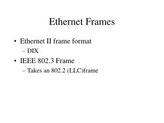
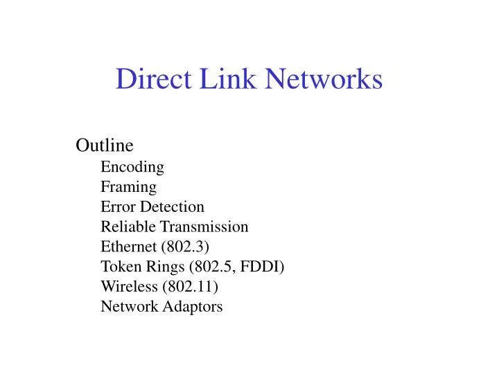
Direct Link Networks. Outline Encoding Framing Error Detection Reliable Transmission Ethernet (802.3) Token Rings (802.5, FDDI) Wireless (802.11) Network Adaptors. Problem: Physically Connecting Hosts. Five issues: Encoding Framing Error detection Reliable delivery Access Mediation

E N D
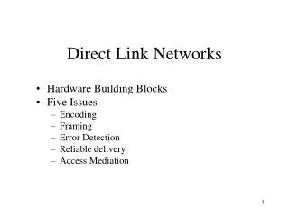
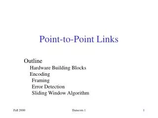
Direct Link Networks Outline Encoding Framing Error Detection Reliable Transmission Ethernet (802.3) Token Rings (802.5, FDDI) Wireless (802.11) Network Adaptors
Problem: Physically Connecting Hosts • Five issues: • Encoding • Framing • Error detection • Reliable delivery • Access Mediation • Goal: • Survey the available network technology • Explore these five fundamental issues
Problem: Physically Connecting Hosts • These five functions are usually implemented in a network adaptor. • Bits are exchanged between adaptors, but correct frames are exchanged between nodes. • Adaptors are controlled by software running on the node – the device driver.
Hardware Building Block • Networks are constructed from nodes and links. • Nodes are often general-purpose computers. • Network links are implemented on a variety of different physical media. • Twisted pair • Coaxial cable • Optical fiber • Space (radio waves, microwaves, infrared beams)
Hardware Building Block • Media is used to propagate signals. These signals are actually electromagnetic waves traveling at the speed of light. • Wavelength = speed / Frequency (Figure 2.2) • A link is said to be full-duplex if two bit streams can be simultaneously transmitted over the link at the same time. A link that supports only one direction is called half-duplex.
Hardware Building Block • Cables (Table 2.1) • Category 5 twisted pair: 10 – 100 Mbps, 100m • Thin-net coax: 10 – 100 Mbps, 200m • Thick-net coax: 10 – 100 Mbps, 500m • Multimode fiber: 100 Mbps, 2m • Single-mode fiber: 100 – 240 Mbps, 40km
Hardware Building Block • Leased Lines • DS1/T1: Digital Signal/Transmission Level 1.544 Mbps • DS3/T3: 44.736 Mbps • STS-N/OC-N: Synchronous Transport Signal/Optical Carrier: 51.84 Mbps ~ 2.48832 Gbps
Hardware Building Block • Last-Mile Links • POTS (Plain Old Telephone System): 28.8-56 Kbps • ISDN (Integrated Services Digital Network): 64-128 Kbps • xDSL (Digital Scriber Line): 16 Kbps – 55.2 Mbps • CATV (Cable TV): 20 – 40 Mbps
Hardware Building Block • Advanced Mobile Phone System (AMPS) has been the standard for celluar phones. • PCS (Personal Communication Services) – USA, Canada • GMS (Global Mobile System) – Rest of the world • Wireless Links (Table 2.4) • ICO • Globalstar • Iridum • Teledesic • Bluetooth is being designed to operate at 2.45 GHz within 10 meters.
Bits 0 0 1 0 1 1 1 1 0 1 0 0 0 0 1 0 NRZ Encoding • Signals propagate over a physical medium • modulate (add the signal to an electronic or optical signal carrier) electromagnetic waves • Modulation can be applied to electric current or voltage (mainly by turning it on and off, e.g., vary voltage) • Encode binary data onto signals • e.g., 0 as low signal and 1 as high signal with with no neutral or rest condition • known as Non-Return to zero (NRZ) (compare to RZ)
Problem: Consecutive 1s or 0s • Low signal (0) may be interpreted as no signal • High signal (1) leads to baseline wander: The baseline distinguishing between low and high signals wanders. • Unable to recover clock: A long period of time without such a transition leads to clock drift.
Alternative Encodings • Non-return to Zero Inverted (NRZI) • make a transition from current signal to encode a one; stay at current signal to encode a zero • solves the problem of consecutive ones • Manchester • transmit XOR of the NRZ encoded data and the clock • Solve the baseline wander and clock drift but only 50% efficient.
Encodings (cont) • 4B/5B (Table 2.5) • every 4 bits of data encoded in a 5-bit code • 5-bit codes selected to have no more than one leading 0 and no more than two trailing 0s • thus, never get more than three consecutive 0s • resulting 5-bit codes are transmitted using NRZI (NRZI solves the problem of consecutive 1s. So reduce 0 in the 5-bit coding.) • achieves 80% efficiency
Bit Rates and Baud Rates • Data Transfer Rate - The time, T, required to transmit one character depends on: • the encoding method • the baud rate (signalling speed) which is the number of times per second that the signal changes its value. • Note: baud rate is not the same as bit rate (Page 80).
Bits 0 0 1 0 1 1 1 1 0 1 0 0 0 0 1 0 NRZ Clock Manchester NRZI Encodings (cont)
Bits Node A Adaptor Adaptor Node B Frames Framing • Break sequence of bits into a frame • Typically implemented by network adaptor
Framing • Byte-oriented protocols • BISYNC (BInary SYNchronous Communication) Protocol: sentinel approach • PPP (Point-to-Point Protocol): sentinel approach • DDCMP (Digital Data Communication Message Control): byte-counting approach • Bit-oriented protocols - HDLC (High-Level Data Link Control) • Clock-Based Framing – Synchronous Optical Network (SONET)
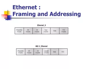
Byte-Oriented Protocols 8 8 8 8 8 16 BISYNC SYN SYN SOH Header STX Body ETX CRC • BISYNC (IBM 1960) (DataLink Protocol) • SYN = synchronization character (start of frame) • SOH = "Start of Header" character • STX/ETX = Start/End-of-Text characters. (What if ETX occurs in Body? char stuff =prefix DataLink Esc) • CRC (Cyclic Redun Chk) field to detect trans errors. • Header: for link-level reliable delivery algorithm.
Byte-Oriented Protocols 8 8 8 16 16 8 PPP Flag Adr Ctrl Prot Payload Chksm Flag • PPP (typically run over dialup networks) (DataLink Protocol) • Flag = 01111110 (Sentinel character) • Adr/Ctrl usually default values (unused) • Protocol identifies high-level protocol (IP, IPX) • Payload (default=1500B or negotiated by LCP) • Checksum field is 2 or 4 bytes (2 default) • LCP (Link Control Protocol): Sends control message encapsulated • PPP uses character stuffing when sentinel occurs in Payload also.
Byte-Oriented Protocols • Couter-based • include payload length in header • e.g., DDCMP (Digital Data Communication Message Control) • problem: count field corrupted • solution: receiver accumulates as many bytes as Count indicates then uses error detection field (e.g., CRC) to determine if it is correct (framing error).
8 16 16 8 Beginning Ending Header Body CRC sequence sequence Bit-Oriented Protocols • It views the frame as a collection of bits. • Sentinel-based • delineate frame with special pattern: 01111110 • e.g., Synchronous Data Link Control (SDLC), HDLC • problem: special pattern appears in the payload • solution: bit stuffing • sender: insert 0 after five consecutive 1s • receiver: delete 0 that follows five consecutive 1s
Clock-based Framing • Synchronous Optical Network (SONET) • The full specification is larger than this book. • It addresses both the framing and encoding problems. • It multiplexes several low-speed links onto one high-speed link.
Clock-based Framing • SONET Frame Structure • 9 x 90 = 810 bytes • First two bytes of the frame contain a special pattern. • Overhead has multiple functions: across different links, specify voice channel, concatenation frames. • Overhead bytes are encoded in NRZ. The payload bytes are scrambled by exclusive-ORing (XOR) a 127 bit pattern. • STS-N frame can be thought of as consisting of N STS-1 frames.
Clock-Based Framing • Clock-based • each frame is 125us long • e.g., SONET: Synchronous Optical Network • STS-n (STS-1 = 51.84 Mbps)
Error Detection • Two approaches can be taken: • Notify the sender to retransmit • Error-correcting code • Techniques for detecting transmission errors • Two-dimensional parity • Checksums • Cyclic redundancy check (CRC): used in nearly all link-level protocol, for example, HDLC, DDCMP, CSMA
Error Detection • The basic idea is to add redundant information that can be used to determine if there is any error. • We can provide quite strong detection capability while sending only k redundant bits for an n-bit message, where k << n. • On a Ethernet, a frame carrying 12,000 bits requires only a 32-bit CRC code. • When the error-detecting algorithm to create the code is based on addition, they may be called a checksum.
Two-Dimensional Parity • 1-D parity adds 1 bit to 7-bit code to balance # of 1s • Odd parity adds a bit so the # of 1-bits is odd. • Even parity adds a bit so the # of 1-bits is even. • 2-D parity does 1-D parity and then the same across each bit of all bytes. • 2-D (even) parity for a 6 byte frame (above) • catches all 1,2,3 bit and most 4-bit errors.
Internet Checksum Algorithm • Add up all the words and then transmit the result of that sum. • View message as a sequence of 16-bit integers; sum using 16-bit ones-complement arithmetic; take ones-complement of the result. u_short cksum(u_short *buf, int count) { register u_long sum = 0; while (count--) { sum += *buf++; if (sum & 0xFFFF0000) { /* carry occurred, so wrap around */ sum &= 0xFFFF; sum++; } } return ~(sum & 0xFFFF); }
Cyclic Redundancy Check • A major goal in designing error detection algorithms is to maximize the probability of detecting errors using only a small number of redundant bits. • In general, correcting is more expensive than detecting and re-transmitting. • Add k bits of redundant data to an n-bit message • want k << n • e.g., k = 32 and n = 12,000 (1500 bytes) • Represent n-bit message as n-1 degree polynomial • e.g., MSG=10011010 as M(x) = x7 + x4 + x3 + x1 • Let k be the degree of some divisor polynomial • e.g., C(x) = x3 + x2 + 1
CRC (cont) • Transmit polynomial P(x) that is evenly divisible by C(x) • shift left k bits, i.e., M(x)xk, append k zero bits to low order end of the frame • subtract remainder of M(x)xk / C(x) from M(x)xk • Suppose that a transmission error E(x) has occurred. Receiver polynomial P(x) + E(x) arrives instead of P(x). P(x) + E(x) / C(x) = E(x)/C(x) • E(x) = 0 implies no errors • Divide (P(x) + E(x)) by C(x); remainder zero if: • E(x) was zero (no error), or • E(x) is exactly divisible by C(x)
CRC Example 11111001 ----------- 1101 /10011010000 <- Message 1101 ----- 1001 1101 ----- 1000 1101 ----- 1011 1101 ---- 1100 1101 ----- 1000 1101 ---- 101 <- Remainder • M(x)=10011010 • C(x)=1101 • k=3 • P(x) = 10011010 101
CRC Example 1100001010 ------------ 10011 /11010110110000 10011 ----- 10011 10011 ----- 10110 10011 ----- 10100 10011 ----- 1110 • M(x)=1101011011 • C(x)=10011 • k=4 • P(x) = 1101011011 1110
Selecting C(x) • All single-bit errors, as long as the xk and x0 terms have non-zero coefficients. • All double-bit errors, as long as C(x) contains a factor with at least three terms • Any odd number of errors, as long as C(x) contains the factor (x + 1) • Any ‘burst’ error (i.e., sequence of consecutive error bits) for which the length of the burst is less than k bits. • Most burst errors of larger than k bits can also be detected • See Table 2.6 on page 102 for common C(x): • CRC-16 = x16+x15+x2+1 => 16 bit check sum. => catches all single,double,odd errors. => catches all burst errors of length <=16
Error Detection or Error Correction • Error correction requires a greater number of redundant bits and is used when: • Errors are quite probable. Wireless. • High cost of the retransmission. A satellite link. • The use of error-correcting codes is sometimes referred as forward error correction (FEC).
Reliable Transmission • The state of the art in error-correcting codes is not advanced enough to handle the range of bit and burst errors without excessive overhead. • Corrupt frames generally must be discarded. • A link-level protocol that delivers frames reliably must recover from these discarded frames. • This is accomplished by acknowledges and timeouts and called automatic repeat request (ARQ).
Reliable Transmission • An acknowledge (ACK) is a small control frame sent back to its peer confirming an earlier frame has been received. A control frame means a header without data. A protocol can piggyback an ACK which is sent back with the data frame. • A timeout is the action of waiting a reasonable amount of time to retransmit a frame. • Three ARQ algorithms are introduced: • Stop-and-Wait • Sliding Window • Concurrent logical channels
Timeline for the stop-and-wait • A timeline is a common way to depict a protocol’s behavior.‘lost’ means the frame was corrupted while in transit.
Stop-and-Wait Sender Receiver • To prevent the duplicate, add 1-bit sequence number in the header. • Shortcoming: have only one outstanding frame. Far below the link’s capacity. • Principle: keeping the pipe full. • Example • 1.5Mbps link x 45ms RTT = 67.5Kb (8KB) • 1KB frames imples 1/8th link utilization
Sender Receiver … ime T … Sliding Window • Allow multiple outstanding (un-ACKed) frames • Upper bound on un-ACKed frames, called window
£ SWS … … LAR LFS SW: Sender • Assign sequence number to each frame (SeqNum) • Maintain three state variables: • send window size (SWS) • last acknowledgment received (LAR) • last frame sent (LFS) • Maintain invariant: LFS - LAR <= SWS • Advance LAR when ACK arrives • Buffer up to SWS frames
£ RWS … … NFE LFA SW: Receiver • Maintain three state variables • receive window size (RWS) • largest frame acceptable (LFA) • last frame received (LFR)/next frame expected (NFE) • Maintain invariant: LFA - LFR <= RWS • Frame SeqNum arrives: • if LFR < SeqNum < = LFA accept • if SeqNum < = LFR or SeqNum > LFA discarded • Send cumulative ACKs
Example of Sliding Window • Example • LFR=5 (i.e. the last ack the receiver sent was for seq no 5) • RWS=4; thus, LAF=9 • If R gets frames 7 and, they are buffered because they are within the window. • Since frame 6 is yet to arrive, Frames 7 and 8 are said to be arriving out of order • If Frame 6 arrived, R sends Ack for 8, sets LFR to 8, and sets LAF to 12.
Example of Sliding Window • Other variations that will improve performance at the cost of complexity: • Ack 5 when Frames 7 and 8 arrived; • NAK for Frame 6 when Frame 7 and 8 arrived • Selective acknowledgement vs. cumulative acks: ack 7 and 8 • Window size: commensurate with bandwidth * delay product. RWS=1 or RWS=SWS. Does make sense to have RWS >SWS?
Sequence Number Space • SeqNum field is finite; sequence numbers wrap around • Sequence number space must be larger then number of outstanding frames • SWS <= MaxSeqNum-1 is not sufficient • suppose 3-bit SeqNum field (0..7) • SWS=RWS=7 • sender transmit frames 0..6 • arrive successfully, but ACKs lost • sender retransmits 0..6 • receiver expecting 7, 0..5, but receives second incarnation of 0..5 • SWS < (MaxSeqNum+1)/2 is correct rule • Intuitively, SeqNum “slides” between two halves of sequence number space • Implementation: Page 109-114
Frame Order and Flow Control • The sliding window protocol is perhaps the best known algorithm in computer networking. • The first role is the one we have been concentrating on in this section - to reliably deliver frames across an unreliable link. • The second role is to preserve the order in which frames are transmitted. • The third role that the sliding window algorithm sometimes plays is to support flow control - a feedback mechanism by which the receiver is able to throttle the sender.
ARPANET - Concurrent Logical Channels • Multiplex 8 logical channels over a each ground link and 16 over each satellite link • Run stop-and-wait on each logical channel • Maintain three state bits per channel • channel busy • current sequence number for the frame to be sent out • next sequence number for the frame coming in • Ground link Header: 3-bit channel number, 1-bit sequence number • 4-bits total • same as sliding window protocol: RWS=SWS
Shared Access Networks Outline Bus (Ethernet 802.3) Token ring (FDDI) Wireless (802.11)
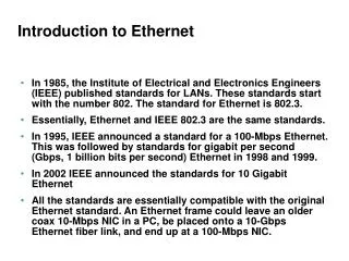
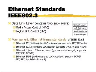
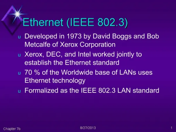
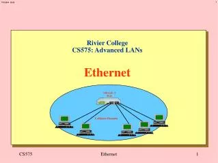
Ethernet Overview • History • developed by Xerox PARC in mid-1970s • roots in Aloha packet-radio network • standardized by Xerox, DEC, and Intel in 1978 • similar to (subset of) IEEE 802.3 standard • CSMA/CD • carrier sense – all nodes can distinguish between an idle and a busy link • multiple access – a set of nodes share a link • collision detection – a node can detect if there is a collision
Ethernet – Physical Properties • Fast Ethernet: 100-Mbps, Gigabit Ethernet: 1 Gbps • 50-ohm coaxial cable (10Base5, thick-net): • A transceiver is a small device tapping to the Ethernet cable. • Multiple Ethernet segments can be joined by repeaters. A repeater is a device that forwards digital signal. • An Ethernet limits 4 repeaters and supports 1024 hosts. • Terminators attached to the end of each segment absorb the signal.
Ethernet – Physical Properties • 10Base2, thin-net • 10 means 10 Mbps. • Base refers to the cable is used in a baseband system. • 2 means a segment not longer than 200m. • T-joint is used. • 10BaseT, Twisted pair • Under 100 m. • Several point-point segments coming out of a multiway repeater, called hub.