Download
1 / 48
480 likes | 640 Views
Point-to-Point Links. Outline Encoding Framing Error Detection Sliding Window Algorithm. Bits. 0. 0. 1. 0. 1. 1. 1. 1. 0. 1. 0. 0. 0. 0. 1. 0. NRZ. Encoding. Signals propagate over a physical medium modulate electromagnetic waves e.g., vary voltage

E N D
Point-to-Point Links Outline Encoding Framing Error Detection Sliding Window Algorithm
Bits 0 0 1 0 1 1 1 1 0 1 0 0 0 0 1 0 NRZ Encoding • Signals propagate over a physical medium • modulate electromagnetic waves • e.g., vary voltage • Encode binary data onto signals • e.g., 0 as low signal and 1 as high signal • known as Non-Return to zero (NRZ)
Problem: Consecutive 1s or 0s • Low signal (0) may be interpreted as no signal • High signal (1) leads to baseline wander • Unable to recover clock
Alternative Encodings • Non-return to Zero Inverted (NRZI) • make a transition from current signal to encode a one; stay at current signal to encode a zero • solves the problem of consecutive ones • Manchester • transmit XOR of the NRZ encoded data and the clock • only 50% efficient (bit rate = 1/2 baud rate)
Bits 0 0 1 0 1 1 1 1 0 1 0 0 0 0 1 0 NRZ Clock Manchester NRZI Encodings (cont)
Encodings (cont) • 4B/5B • every 4 bits of data encoded in a 5-bit code • 5-bit codes selected to have no more than one leading 0 and no more than two trailing 0s • thus, never get more than three consecutive 0s • resulting 5-bit codes are transmitted using NRZI • achieves 80% efficiency
Bits Node A Adaptor Adaptor Node B Frames Framing • Break sequence of bits into a frame • Typically implemented by network adaptor
8 16 16 8 Beginning Ending Header Body CRC sequence sequence Approaches • Sentinel-based • delineate frame with special pattern: 01111110 • e.g., HDLC, SDLC, PPP • problem: special pattern appears in the payload • solution: bit stuffing • sender: insert 0 after five consecutive 1s • receiver: delete 0 that follows five consecutive 1s
Approaches (cont) • Counter-based • include payload length in header • e.g., DDCMP • problem: count field corrupted • solution: catch when CRC fails
Approaches (cont) • Clock-based • each frame is 125us long • e.g., SONET: Synchronous Optical Network • STS-n (STS-1 = 51.84 Mbps)
Cyclic Redundancy Check • Add k bits of redundant data to an n-bit message • want k << n • e.g., k = 32 and n = 12,000 (1500 bytes) • Represent n-bit message as n-1 degree polynomial • e.g., MSG=10011010 as M(x) = x7 + x4 + x3 + x1 • Let k be the degree of some divisor polynomial • e.g., C(x) = x3 + x2 + 1
CRC (cont) • Transmit polynomial P(x) that is evenly divisible by C(x) • shift left k bits, i.e., M(x)xk • subtract remainder of M(x)xk / C(x) from M(x)xk • Receiver polynomial P(x) + E(x) • E(x) = 0 implies no errors • Divide (P(x) + E(x)) by C(x); remainder zero if: • E(x) was zero (no error), or • E(x) is exactly divisible by C(x)
Selecting C(x) • All single-bit errors, as long as the xk and x0 terms have non-zero coefficients. • All double-bit errors, as long as C(x) contains a factor with at least three terms • Any odd number of errors, as long as C(x) contains the factor (x + 1) • Any ‘burst’ error (i.e., sequence of consecutive error bits) for which the length of the burst is less than k bits. • Most burst errors of larger than k bits can also be detected • See Table 2.6 on page 102 for common C(x)
Internet Checksum Algorithm • View message as a sequence of 16-bit integers; sum using 16-bit ones-complement arithmetic; take ones-complement of the result. u_short cksum(u_short *buf, int count) { register u_long sum = 0; while (count--) { sum += *buf++; if (sum & 0xFFFF0000) { /* carry occurred, so wrap around */ sum &= 0xFFFF; sum++; } } return ~(sum & 0xFFFF); }
Stop-and-Wait Sender Receiver • Problem: keeping the pipe full • Example • 1.5Mbps link x 45ms RTT = 67.5Kb (8KB) • 1KB frames implies 1/8th link utilization
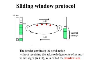
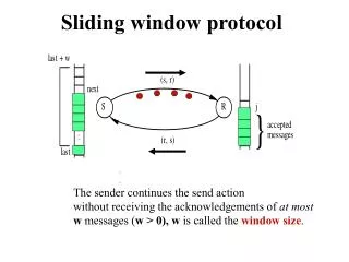
Sender Receiver … ime T … Sliding Window • Allow multiple outstanding (un-ACKed) frames • Upper bound on un-ACKed frames, called window
£ SWS … … LAR LFS SW: Sender • Assign sequence number to each frame (SeqNum) • Maintain three state variables: • send window size (SWS) • last acknowledgment received (LAR) • last frame sent (LFS) • Maintain invariant: LFS - LAR <= SWS • Advance LAR when ACK arrives • Buffer up to SWS frames
£ RWS … … NFE LFA SW: Receiver • Maintain three state variables • receive window size (RWS) • largest frame acceptable (LFA) • last frame received (NFE) • Maintain invariant: LFA - LFR <= RWS • Frame SeqNum arrives: • if LFR < SeqNum < = LFA accept • if SeqNum < = LFR or SeqNum > LFA discarded • Send cumulative ACKs
Sequence Number Space • SeqNum field is finite; sequence numbers wrap around • Sequence number space must be larger then number of outstanding frames • SWS <= MaxSeqNum-1 is not sufficient • suppose 3-bit SeqNum field (0..7) • SWS=RWS=7 • sender transmit frames 0..6 • arrive successfully, but ACKs lost • sender retransmits 0..6 • receiver expecting 7, 0..5, but receives second incarnation of 0..5 • SWS < (MaxSeqNum+1)/2 is correct rule • Intuitively, SeqNum “slides” between two halves of sequence number space
Concurrent Logical Channels • Multiplex 8 logical channels over a single link • Run stop-and-wait on each logical channel • Maintain three state bits per channel • channel busy • current sequence number out • next sequence number in • Header: 3-bit channel num, 1-bit sequence num • 4-bits total • same as sliding window protocol • Separates reliability from order
Shared Access Networks Outline Bus (Ethernet) Token ring (FDDI) Wireless (802.11)
Gedankenexperiment • How does communication work in real life? • If there are lots of speakers/speaking? • If there is little speaking? • If there are “important” people? • Can we map this to computer networks?
64 48 48 16 32 Src Dest Preamble Type Body CRC addr addr Ethernet Overview • History • developed by Xerox PARC in mid-1970s • roots in Aloha packet-radio network • standardized by Xerox, DEC, and Intel in 1978 • similar to IEEE 802.3 standard • CSMA/CD • carrier sense • multiple access • collision detection • Frame Format
Ethernet (cont) • Addresses • unique, 48-bit unicast address assigned to each adapter • example: 8:0:e4:b1:2 • broadcast: all 1s • multicast: first bit is 1 • Bandwidth: 10Mbps, 100Mbps, 1Gbps • Length: 2500m (500m segments with 4 repeaters) • Problem: Distributed algorithm that provides fair access
Transmit Algorithm • If line is idle… • send immediately • upper bound message size of 1500 bytes • must wait 9.6us between back-to-back frames • If line is busy… • wait until idle and transmit immediately • called 1-persistent (special case of p-persistent)
Algorithm (cont) • If collision… • jam for 32 bits, then stop transmitting frame • minimum frame is 64 bytes (header + 46 bytes of data) • delay and try again • 1st time: 0 or 51.2us • 2nd time: 0, 51.2, 102.4, or 153.6us • nth time: k x 51.2us, for randomly selected k=0..2n - 1 • give up after several tries (usually 16) • exponential backoff
Collisions A B A B A B A B
Token Ring Overview • Examples • 16Mbps IEEE 802.5 (based on earlier IBM ring) • 100Mbps Fiber Distributed Data Interface (FDDI)
8 8 48 48 8 32 24 Start of Dest Src End of Control Body CRC Status frame addr addr frame Token Ring (cont) • Idea • Frames flow in one direction: upstream to downstream • special bit pattern (token) rotates around ring • must capture token before transmitting • release token after done transmitting • immediate release • delayed release • remove your frame when it comes back around • stations get round-robin service • Frame Format
Timed Token Algorithm • Token Holding Time (THT) • upper limit on how long a station can hold the token • Token Rotation Time (TRT) • how long it takes the token to traverse the ring • TRT <= ActiveNodesxTHT + RingLatency • Target Token Rotation Time (TTRT) • agreed-upon upper bound on TRT
Algorithm (cont) • Each node measures TRT between successive tokens • if measured-TRT > TTRT: token is late so don’t send • if measured-TRT < TTRT: token is early so OK to send • Two classes of traffic • synchronous: can always send • asynchronous: can send only if token is early • Worse case: 2xTTRT between seeing token • Back-to-back 2xTTRT rotations not possible
Token Maintenance • Lost Token • no token when initializing ring • bit error corrupts token pattern • node holding token crashes • Generating a Token (and agreeing on TTRT) • execute when join ring or suspect a failure • send a claim frame that includes the node’s TTRT bid • when receive claim frame, update the bid and forward • if your claim frame makes it all the way around the ring: • your bid was the lowest • everyone knows TTRT • you insert new token
Maintenance (cont) • Monitoring for a Valid Token • should periodically see valid transmission (frame or token) • maximum gap = ring latency + max frame < = 2.5ms • set timer at 2.5ms and send claim frame if it fires
Wireless Technologies Most commonly used wireless technologies: • Wi-Fi (802.11) • Bluetooth (802.15.1) • WiMAX (802.16) • 3G Cellular 35
Wireless Technologies Physical Considerations of wireless protocols: • Bandwidth Capabilities • Transmission Distance Limitations (Range) • Frequency/Power/License 37
Wireless Technologies •Well suited for multiple clients as one base station can transmit and receive with multiple clients. •Common to all of these technologies is the fixed point.
Bluetooth 802.15.1 One Master device 7 Active slave devices 255 Parked Devices License Exempt band of 2.45 GHz Low Power Consumption Protocol implemented beyond link level -Where it defines application protocols via use of profiles -Profiles are application level protocols for different types of device connections. -Hands Free Devices -Hardware and peripherals -PDA Synchronization
Wi-Fi 802.11 802.11a ->5 GHz band OFDM (Orthogonal Frequency division Multiplexing) Direct sequence easily absorbed by environment, limited to line of sight 802.11b -> Variant of direct sequence 802.11g ->OFDM (Orthogonal Frequency division Multiplexing) Backward compatible with 802.11b
Wi-Fi 802.11 Functional Aspects of Wi-Fi Each host has an assigned access point. Access point is fixed. Collision avoidance- (not detection) Problem: If each host has its own link, how do we determine if the link is busy? (It is the receiver that must be determined to be free or busy.) Examples: Hidden nodes and Exposed nodes Solution: MACA (multiple access with collision avoidance).
Wi-Fi 802.11 Functional Aspects of Wi-Fi MACA- Control Frames- Exchange of RTS and CTS frames RTS –Comes from source, requesting access CTS – Comes from recipient, granted access Note: RTS–contains a field that indicates the amount of time the sender is requesting. Exchange of the CTS frame informs surrounding nodes that are in range that they cannot transmit during the period of time that it takes to transmit that one frame and to send and ACK. Question: What if we have to hosts that send and RTS message that results in a collision at the host? Answer: When the timeout period expires each host will make the determination that a collision has occurred at the host ( the host does not have any collision detection in 802.11). Thus each will resend according to an exponential back off algorithm.
Wi-Fi 802.11 Distribution System: Active Scanning: Host sends out a probe frame, analyzes responses from AP’s Passive Scanning: AP sends out Beacon frame that advertises capabilities. Host evaluates current situation and stays or sends out an association request to be associated with the new AP.
Wi-Fi 802.11 • Frame Formats: • Control Field: • Contains 3 Sub fields • TYPE Field: Indicates whether frame carries data or identifies itself as a RTS or CTS frame. • ToDS one bit field • FromDS one bit field
Wi-Fi 802.11 Addr1 in the most simple cases, is the destination address. Addr2 in the most simple cases, is the source address. In the Event that the DS bits are not 0, this indicates that the frame has been forwarded by more than one node, thus the sender’s address is not necessarily the origination address. Thus we have 4 fields for addresses.
Wi-MAX 802.16 Worldwide interoperability for Microwave Access -Intended as a “Last Mile” Technology. Offers 70Mbps connections when connected to subscriber stations. Requires Line of Sight for connection. Not a mobile technology, both access point and host are stationary. 10-66 GHz Range(licensed and unlicensed) Base station transmits to all hosts, hosts pick what belongs to them and ignore the rest. This simplifies the outbound transmissions (only the transmitter takes up outbound slots). Incoming slots are shared among all hosts, this includes other WiMAX stations. QOS can be implemented to garuntee quality for voice communications. Under this concept slots are dynamically allocated to some requesters.
Wi-MAX 802.16 Two ways of dividing the bandwidth between upstream and down stream: TDD: STDM of the up and down streams. FDD: FDM of the up and down streams.
3G CDMA (most commonly used in the US)is a 2G technology that uses chipping codes instead of FDM or TDM on the physical link layer. Speed is limited as time slots and compression algorithms are geared towards compressing human speech. Thus they are not optimized for data. GSM (Europe) also a 2 G technology used GPRS for data had better data rates as more time slots could be allocated if available for data. 3G: technolgy is still emerging and has yet to be truly standardized, but one promising standard is UMTS. UMTS-Based on W-CDMAs, 1.9 Mpbs