Download
1 / 17
170 likes | 283 Views
Considerations on 3 - 4 GeV H- injection for PS2. Basic considerations Injection system geometry Chicane Injection Extraction of H 0 and H - beams Foil issues Thickness & efficiency Heating Emittance blow-up. Basics . 40 mA SPL. 20 mA SPL. Injection system geometry.

E N D
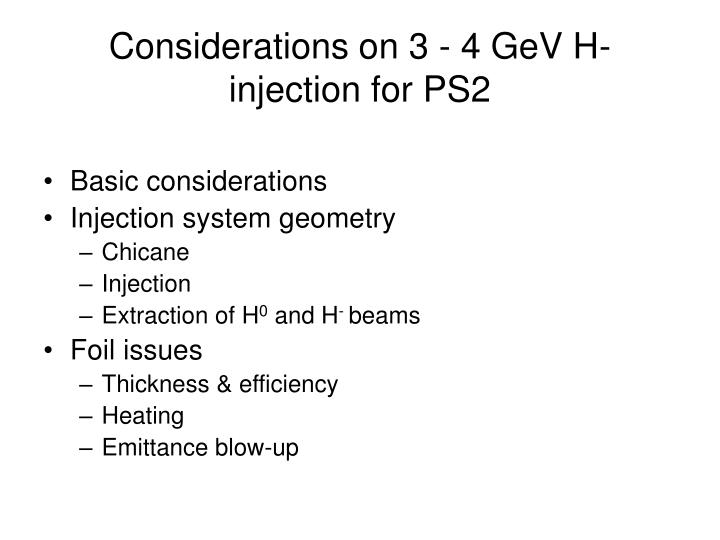
Considerations on 3 - 4 GeV H- injection for PS2 • Basic considerations • Injection system geometry • Chicane • Injection • Extraction of H0 and H- beams • Foil issues • Thickness & efficiency • Heating • Emittance blow-up
Basics 40 mA SPL 20 mA SPL
Injection system geometry • Had assumed in 1.5 FODO cells (a la JPARC) Injection septum ½ cell Chicane & stripping foil ½ cell Dump septum ½ cell beam
Limits • Lorentz stripping • Injection septum <0.14 T • Bend angle ~9 mrad/m • Need full half-cell for septum • Injection chicane • First 2 dipoles deflect main H- beam – need <0.14 T • Second 2 see unstripped H0 and H- - could make stronger?
Chicane ½ cell geometry 10.0 m beam Foil 2 Foil 1 ~70 mm ~23 mm 1.0 m 2.5 m 1.0 m 9.0 mrad QD QF • 23 mm chicane bump, 23 mm painting bump (4 other magnets….) • 1.0 m long magnets with 2.5 m centres give ~9 mrad and ~23 mm • Foil edge at about 40 mm – just outside ‘aperture’ (50 mm x b/bmax)
Injection septum ½ cell geometry • Covered by Wolfgang • ½ cell full of septum - at limit (8 m magnetic in ~10 m drift) • Seems preferable to not rely on injecting through quad coil window (aperture, extra fields, constraints, quad design) beam 570 mm 60 mm 2.0 m, 18.0 mrad Difficult (but maybe not impossible!) to get past upstream quad yoke and into the downstream quad aperture
H-/H0 dump ½ cell geometry To dump beam 2.0 m, 130 mrad ~3.0 m QF QD • Can use ‘real’ septum (>1.0 T); easy to get beam out (2 m 130 mrad) • ~5 kW of protons – need large acceptance TL….or internal dump? • Only use about half of the ½ cell
Alternative geometries… • Also will investigate injection system insertion between doublets (a la SNS)? • flat b functions between lattice quads • Fit whole injection system (septa, chicane) into this drift • Avoid problems with lattice quads • Generate enough space in insertion?
Painting and foils • Linear painting functions with anti-correlated H/V CNGS beam, 135 turns LHC beam, 60 turns
Foil thickness & efficiency 4 GeV • assume thickness of 400-500 ug/cm2 and H0 yield of about 2% • detailed scaling needed to check 3 and 4 GeV cases
Foil heating and hits Assuming injected H- beam deposits ~2.4 times dE/dx as p+ (p+ dE/dx is 1.75 MeV/g/cm2, e- dE/dx is 1.2 MeV/g/cm2) DT ~1540 K! CNGS 135 turns,1210 K, 9.7 hits/p+ CNGS 270 turns,1540 K, 17.8 hits/p+ LHC 60 turns, 820 K, 10.2 hits/p+ LHC 120 turns, 1240 K, 17.2 hits/p+
Repeated heating • Not an issue for 2.4 s period (0.5 s gives extra 100 K) T [K] t [s]
Emittance growth and losses (3 GeV) Loss < 0.02 % Den < 0.1 p.mm.mrad …not an issue
Conclusion/outlook/remarks • First studies under way…system is a challenge! • Try and fit into FODO structure • H-painting with 23 mm bump – 4 magnets outside chicane ½ cell • Vertical painting with ~1 mrad angle – bumper/kickers needed • ~500 mg/cm2 foil assumed to be needed (~3 mm thick) • Few % of unstripped H0 to extract with septum and transfer to dump - ~5 kW • Painting very ‘slow’ to maintain emittance (need ~1000 turns fall for LHC) • Increasing injected turns by factor of 2 makes injection more difficult • Foil hits ~double (18 per p+) and high foil heating (>1400 K DT) • Emittance blow-up quite small (<0.05 Den) • Beam losses from nuclear scattering <2x10⁻⁴ level • To avoid too-high p+ density at foil assumed large (~15 m) bs at end of TL (H- beam size). • Injection system fields max 0.14 T – complicates geometry (fill ½ cells…) • Much more study and optimization needed….!
Next steps • More rigorous conceptual design in FODO structure • Use baseline optics • Trajectories, envelopes and apertures • Warning from SNS – do this properly from start! • Painting optimisations, foil physics • Dump – internal/external + TL? • Longitudinal painting – dispersion limits for lattice/TL • Large aperture quad feasibility • Start investigating Doublet insertion – pros/cons