Download
1 / 11
110 likes | 243 Views
New CLIC joint - study status. Przemyslaw Lutkiewicz Cedric Garion (supervisor). 1. CLIC - joint demand . Requirements: Quantity – about 500 000 units Reliable joint - high sealing performance Smooth flange-gasket-flange transition ( RF )

E N D
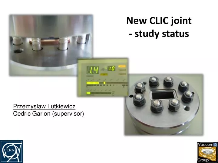
New CLIC joint - study status Przemyslaw Lutkiewicz Cedric Garion (supervisor)
1. CLIC - joint demand • Requirements: • Quantity – about 500 000 units • Reliable joint - high sealing performance • Smooth flange-gasket-flange transition ( RF ) • Simple shapes and preferably symmetrical joint • Easy in assembly • Cheap in production • Przemyslaw Lutkiewicz AT/VAC ; Przemyslaw.Lutkiewicz@cern.ch
2. Existing design concept flange • Based on SLAC X-band joint and stainless steal WR90 flanges and OFC copper gasket: • Not symmetrical gasket cross-section • Two different flanges • Main sealing mechanism comes from shearing not compression • flanges clumped with 8 bolts gasket flange Existing design concept CLIC gasket vs 2 CHF coin Przemyslaw Lutkiewicz AT/VAC
3. Existing design drawback No sealing Sealing No sealing • Drawbacks are mainly related with non symmetrical : • Large and non constant displacements into gasket aperture • Different contact pressure distribution for upper and lower surface of the gasket • Trapped volume • Problematic in assembly and production Sealing No sealing Upper surface 0.25 Contact pressure between upper gasket surface and flange Sealing Sealing No sealing Joint concept 0.25 Sealing Trapped volume Contact pressure near grove Lateral profile of the maximum inner displacements No sealing Sealing Contact pressure between upper gasket surface and flange No sealing CLIC gasket vs 2 CHF coin Contact pressure between lower gasket surface and flange • Przemyslaw Lutkiewicz AT/VAC ; Przemyslaw.Lutkiewicz@cern.ch
4. New design concept flange • Rectangular in cross-section OFS copper gasket • Symmetrical, “knife” based design • Conical side – higher slope • Flat side – low slop • Initial gasket position back from flange-flange aperture face • SS 316LN flanges with 8 screws and two locating pins gasket Assembled joint Symmetry New CLIC design concept Przemyslaw Lutkiewicz AT/VAC
5. New design benefits • Homogeneous contact pressure –the joint is symmetric type (sexless) • Cheaper production –simple and easy to machine gasket shape and one type of flange • Easier assembly –symmetric, self-placed gasket with additional pins centering joint system • Superior RF properties – smooth flange-gasket-flange transition Old design New proposal 0.25 mm Flange Flange self-placed gasket + Pins centering joint system self-placed gasket 1) 1) > 0.1 mm 2) 2) Gasket Gasket 3) 1) Female flange Gasket with moderate shape Male flange One type of flange Gasket with simple shape Flange SYMMETRY NO SYMMETRY Flange 0.15 mm • Przemyslaw Lutkiewicz AT/VAC ; Przemyslaw.Lutkiewicz@cern.ch
6. Geometrical optimization • Theoretical leak rate • Optimization of geometrical parameters based on a2D axis-symmetrical FE model • Total leak rate flange Beta (Q2) Alpha (Q1) gasket Initial position thickness Geometrical parameters Przemyslaw Lutkiewicz AT/VAC
7. Experimental tests • The leak tightness test: • Before optimization : • <1.4e-10 mbar L/ s • ~60% to 100% of clumping disp. • Confirmed 4 times • After optimization : • <5.6e-11 mbarL/s • ~60-115% of clumping disp. • Confirmed 3 times The leak tightness level • Displacement into aperture: • Before optimization : • 0.08 mm @ 0.30 mm imprint depth • Flange’s knifes plastically deformed • After optimization : • 0.03mm @ 0.33 mm imprint depth • Flange - no plastic deformation Joint at the experiment • Przemyslaw Lutkiewicz AT/VAC ; Przemyslaw.Lutkiewicz@cern.ch
8. Results from 3D FE model Displacement into the aperture • The displacement into aperture as an input for future RF calculations Przemyslaw Lutkiewicz AT/VAC
9. Future steps With width like old design • RF checking based on the 3D FE model results • RF experimental checking • Definition of flange parameters : • Thickness • Number of bolts and placing • Decide the final tolerances • Final testing With width like 1/3 of old design • Przemyslaw Lutkiewicz AT/VAC ; Przemyslaw.Lutkiewicz@cern.ch
THE END With width like old design With width like 1/3 of old design Thanks for Your attention • Przemyslaw Lutkiewicz AT/VAC ; Przemyslaw.Lutkiewicz@cern.ch