Download
1 / 33
330 likes | 451 Views
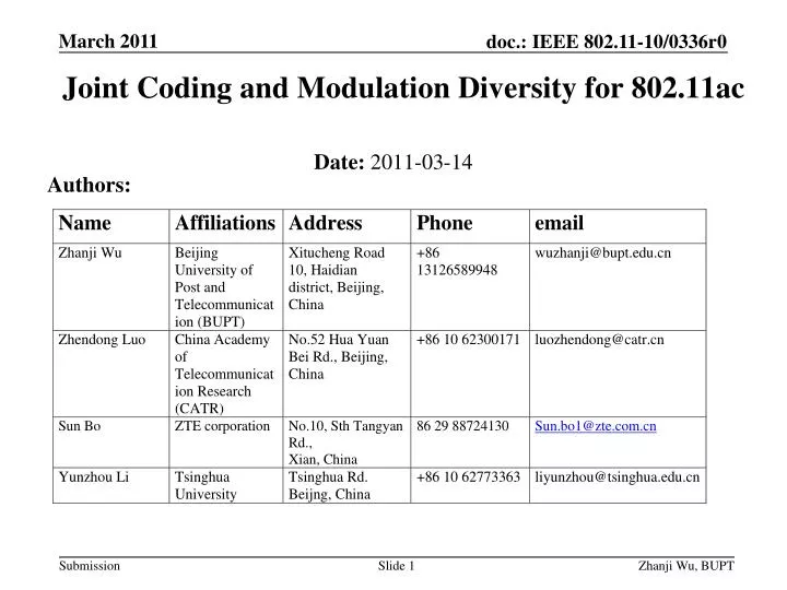
Joint Coding and Modulation Diversity for 802.11ac. Authors:. Date: 2011-03-14. Abstract.

E N D
Joint Coding and Modulation Diversity for 802.11ac Authors: Date: 2011-03-14
Abstract • In 802.11ad system, according to the IEEE 802.11-10/0433r2 document, the rotation modulation technique has already been adopted in QPSK modulation. Based on our recent research, this technique can also improve the overall performance of 802.11ac system, especially in MIMO-OFDM scenario. Therefore, we recommend to introduce this technique to 802.11ac system.
Transmitter/Receiver Block Diagram NOTES — Red block is our proposed amendment. —There may be 1 or 2 FEC encoders when BCC encoding is used. —When LDPC encoding is used, the interleavers are not used.
Amendment and simulation are based on the document IEEE 802.11n-2009 and IEEE 802.11-09/0992r18. In the amendment, we use rotational modulation method to combine with time diversity of channel coding, spatial diversity of MIMO and frequency diversity of OFDM, which is named joint coding and modulation diversity (JCMD) . As compared with JCMD, the processing scheme in IEEE 802.11n Standard is named bit interleaved coded modulation (BICM) for simplicity.
Basic principle of the rotational modulation • According to rotational matrix,rotate the conventional modulated symbol. • The relationship between conventional modulated complex symbol A + j*B and the rotational modulated complex symbol X + j*Y is shown in equation: • where A and B are the I (in-phase) and Q (quadrature) component of the normal QAM, respectively; X and Y are the I and Q component of rotated QAM, respectively
Basic principle of the Spatial Interleaving • In this process , denotes rotated symbol on the stream at time sample. So the interleaving is usual spiral layer interleaving process among all streams at the same time. The method is as follow: • Where is the number of spatial streams. • For example, consider the case, =4: • Corresponding, uses the inverse algorithm at the receiver as follow:
Basic principle of the Spatial Q-Interleaving • In the spatial Q-interleaving process, I components of the complex signals are unchanged, while Q components of signals are changed as follows: • That is to say, Q component on stream i will be moved to the stream (Nss-i-1). • Corresponding, use the inverse algorithm at the receiver, which is the same as above spatialQ-Interleaving equation
Basic principle of the Frequency domainQ-interleaveing • In the frequency domain Q-interleaving process, the I components of the complex signals are unchanged, while Q components of signals are changed as follows: • is the number of subcarriers for data. • That is to say, Q component on subcarrier i will be moved to the subcarrier (Nss-i-1). • Corresponding, uses the inverse algorithm at the receiver, which is the same as above frequency Q-interleaving equation.
Basic principle of Beamforming • According to the theory of SVD,the channel matrix H can be decomposed as where D is a non-negative diagonal matrix of . • Pre-coding: • For example, we assume
Basic principle of Pre-decoding • The received signal vector is modeled as shown in Equation . • SVD-decoding: • So • For each stream,
Basic principle of demodulation • Due to spatial Q-interleaving and frequency Q-interleaving, fading coefficient of I component is usually different from that of Q component .
Basic principle of demodulation • For example, consider the R-QPSK(rotational quadrature phase-shift keying): • The procedure for demodulation is shown as follows: • Compute the distance between the received point and each reference constellation point. The relationship between the reference constellation point and the rotational constellation point is shown as follows: so
Basic principle of demodulation • 2) Compute the Likelihood ratio (LLR) for every bit. The LLR is the input of the decoder. • For the first bit : • For the second bit: • There is also a simplified algorithm to compute the LLRs: • Similarly, for M-ary QAM(Quadrature amplitude modulation), we should compute LLRs for bits.
Rotation Modulation LOS (2*2),LDPC vs BCC • LDPC-coded BICM with much higher complexity only obtains 0.72 dB SNR gain as compared with BCC-coded BICM. • BCC-coded JCMD with much lower complexity obtains significant 6.72 dB SNR gain as compared with LDPC-coded BICM.
Rotation Modulation NLOS (2*2),LDPC vs BCC • LDPC-coded BICM with much higher complexity only obtains 0.48 dB SNR gain as compared with BCC-coded BICM. • BCC-coded JCMD with much lower complexity obtains significant 6.76 dB SNR gain as compared with LDPC-coded BICM.
Effect of phase noise • The phase noise will be specified with a pole-zero model. PSD(0) = -100 dBc/Hz pole frequency fp = 250 kHz zero frequency fz = 7905.7 kHz This model results in PSD(infinity) = -130 dBc/Hz,
Effect of Amplitude distortion • The PAPR (Peak to Average Power Ratio) and Cubic Metric of JCMD are almost the same as that of BICM, so amplitude distortion does not change the relative gain.
Hardware Platform • The platform • Rohde&Schwarz AMU (fading simulator) • 2*FSV(signal analyzer) • 2*SMBV(vector signal generator) • PicoChip PC203 Baseband Unit
Hardware Simulation Results • SISO: JCMD obtains 2 .1dB SNR gain at FER=0.01 as compared with BICM.
Conclusions • The proposed JCMD can achieve obvious SNR gain (up to 7.25dB) over the current 802.11ac schemes in all the secenarios (including LOS and NLOS channels, BCC and LDPC). • Even the JCMD using BCC can obtain significant SNR gain (up to 6.7dB) over the current 802.11ac schemes using LDPC. • For 2*2 ,4 * 4 and 8 * 8 antenna schemes, JCMD can keep the similar SNR gains. • The phase and amplitude distortions do not change the relative gains. • In a word, JCMD is simple, efficient, robust and energy-saving, thus is suitable for 802.11ac to realize“Green Communication”.
Strawpoll • Do you accept JCMD as an optional enhanced coded modulation scheme for 802.11ac ? -Yes -No -Abstain
References • IEEE P802.11 Wireless LANs PHY/MAC Complete Proposal Specification, 2010-05-18 • Erceg, V. et al. “TGn Channel Models.” Doc. IEEE802.11-03/940r4. • Breit, G. et al., “TGac Channel Model Addendum,” Doc.IEEE 802.11-09/0308r12 • IEEE 802.11n-2009 • IEEE 802.11-09/0992r18