Download
1 / 34
380 likes | 681 Views
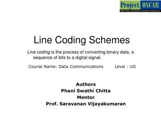
Line Coding and Binary Keying Modulation. Amplitude. 0. 1. 0. 0. 1. 1. 0. 1. Time. (a) Two signal level and two data level. Amplitude. 0. 1. 0. 0. 1. 1. 0. 1. Time. (b) Three signal level and two data level. Some Characteristics of Line Coding. Signal level and Data Level.

E N D
Amplitude 0 1 0 0 1 1 0 1 Time (a) Two signal level and two data level Amplitude 0 1 0 0 1 1 0 1 Time (b) Three signal level and two data level Some Characteristics of Line Coding Signal level and Data Level
Bit Rate and Pulse rate • If a pulse carries only 1 bit, the pulse rate and the bit rate are the same. If the pulse carries more than 1 bit, then the bit rate is greater than the pulse rate. In general we have the following formula, in which L is the number of data levels of the signal..
Amplitude 0 1 0 0 1 1 0 1 Time (a) Signal with DC components Amplitude 0 1 0 0 1 1 0 1 Time (b) Signal without DC components DC component
Synchronization • In order to correctly interpret the signals received from the sender, the receiver's bit intervals must correspond exactly to the sender's bit intervals. If the receiver clock is faster or slower, the bit intervals are not matched and the receiver might interpret the signals differently than the sender intended. • A self-synchronizing digital signal includes timing information in the data being transmitted. This can be achieved if there are transitions in the signal that alert the receiver to the beginning, middle, or end of the pulse. If the receiver's clock is out of synchronization, these alerting points can reset the clock.
Amplitude 0 1 0 0 1 1 0 1 Time Sent Amplitude 0 0 1 0 0 0 0 1 1 1 0 1 1 Time Received
Line Coding Unipolar Polar Bipolar
Amplitude Amplitude 0 1 Time Time (a) Logic 0 (b) Logic 1 Amplitude 0 1 1 1 0 0 1 0 Time (c) Timing diagram Unipolar
Polar NRZ RZ Manchester Differential Manchester Polar
Amplitude Amplitude 0 1 Time Time (a) Logic 0 (b) Logic 1 Amplitude 0 1 1 1 0 0 1 0 Time (c) Timing diagram Nonreturn to Zero-Level(NRZ-L)
Logic 0 - No Transition from current state Logic 1- Transition from current state to different state Amplitude 0 1 1 1 0 0 1 0 Time Nonreturn to Zero-Invert(NRZ-I)
This transition is used for synchronization Amplitude Amplitude 0 1 Time Time (a) Logic 0 (b) Logic 1 Amplitude 0 1 1 1 0 0 1 0 Time (c) Timing diagram Return to Zero(RZ)
Amplitude Amplitude 0 1 Time Time (a) Logic 0 (b) Logic 1 Amplitude 0 1 1 1 0 0 1 0 Time (c) Timing Diagram Manchester Encoding
Logic 0 - Transition from current state to different state Logic 1- Continuation of current state i.e. no transition Amplitude 0 1 1 1 0 0 1 0 Time Differential Manchester Encoding
Logic 0 – Level Zero Logic 1- Levels are positive and negative alternately Amplitude 0 1 1 1 0 0 1 0 Time Bipolar
Amplitude 11 10 01 00 10 11 00 01 3 1 0 Time -1 -3 Two binary, one quaternary (2B1Q)
Amplitude 0 1 1 1 0 0 1 1 1 1 1 1 0 1 0 Time Multiline transmission, three level (MLT-3)
010111010101 ...01011110 n Bits n Bits n Bits m Bit Division 01101 10101 011011 m Bits m Bits m Bits Line coding 0101 1101 1110 m Bit to n Bit Substitution Digital signal Block Coding
4-bit Blocks 5-bit Blocks 0000 00000 0001 00011 0010 00010 1000 10000 1111 11011 11111 4B/5B encoding • With a 4-bit block, we can have 16 (=24) different groups. With a 5-bit code, there are 32 (=25) possible codes. This means that we can map some of the 5-bit groups to the 4-bit groups. Some of the 5-bit codes are not used. We can apply a strategy or a policy to choose only the 5-bit codes that help us in synchronization and error detection.
To achieve synchronization, we can use the 5-bit codes in such a way that, for example, we do not have more than three consecutive 0s or 1s. Block coding can definitely help in error detection. Because only a subset of the 5-bit codes is used, if one or more of the bits in the block is changed in such a way that one of the unused codes is received, the receiver can easily detect the error. • The selection of the 5-bit code is such that each code contains no more than one leading 0 and no more than two trailing 0s. Therefore, when these 5-bit codes are sent
Digital to Analog Modulation ASK FSK PSK QAM Types of methods • Amplitude shift keying (ASK): some audio modem, optical fiber, printer • Frequency shift keying (FSK): Computer Modem, HF and VHF radio • Amplitude shift keying (PSK): Mobile, Satellite (microwave) etc Bit rate is the number of bits transmitted per second. Baud rate is the number of signal elements transmitted per second. Baud rate is less than or equal to the bit rate
Amplitude 1 Bit 1 1 Bit 0 1 Bit 1 1 Bit 0 1 Bit 1 1 Bit 0 Time 1 Baud 1 Baud 1 Baud 1 Baud 1 Baud 1 Baud 1 Sec Bit rate: 6 Baud rate: 6 ASK The carrier with unity amplitude Mathematically ASK waveform can be written as
The bandwidth which needs to be transmitted depends on the requirements of the application. Where there is a need to recover recognizably square pulses at the receiver (to operate a printer), it may be necessary to include at least the third harmonic sideband pair This leads to the criterion
Example • The standard symbol speed of 66 words per minute used by many automatic teletype machines. This corresponds to 50 baud (symbol rate) per second which need an f0=25 Hz. Thus its 3rd harmonic BW is 75Hz or 120 Hz with guard band. • But where all that is needed is to be able to decide whether a one or a zero was received and an exact bit shape is not required.
Amplitude 1 Bit 1 1 Bit 0 1 Bit 1 1 Bit 0 1 Bit 1 1 Bit 0 Time 1 Baud 1 Baud 1 Baud 1 Baud 1 Baud 1 Baud 1 Sec Bit rate: 6 Baud rate: 6 FSK Where s2(t) is the complement of s1(t) so that s2(t)=1- s1(t)
PSK • PSK has advantages over both ASK and FSK. • It has the same BW as ASK which is of course less than that of FSK. • It is less susceptible to noise corruption than FSK and of course very much better than ASK • BW reduced by multilevel scheme.
01 00 11 10 Dibits (2 Bits) 010 Constellation Diagram Tribit Phase 000 0o 00145o 010 90o 011 135o 100 180o 101 225o 110 270o 111 315o 011 001 000 100 101 111 110 Constellation Diagram
Amplitude 2 Bits 00 2 Bits 11 2 Bits 01 2 Bits 10 2 Bits 00 2 Bits 10 Time 1 Baud 1 Baud 1 Baud 1 Baud 1 Baud 1 Baud 1 Sec Bit rate: 12 Baud rate: 6 4PSK
011 01 00 010 101 000 100 001 10 11 110 111 4-QAM 1 Amplitude, 4 Phases 8-QAM 2 Amplitudes, 4 Phases 4QAM
Amplitude 3 Bits 3 Bits 3 Bits 3 Bits 3 Bits 3 Bits 3 Bits 3 Bits 000 001 011 010 110 111 101 100 Time 1 Baud 1 Baud 1 Baud 1 Baud 1 Baud 1 Baud 1 Baud 1 Baud 1 Sec Bit rate: 24 Baud rate: 08 8QAM
16 QAM 16 QAM 16 QAM 3 Amplitudes 12 Phases 2 Amplitudes 8 Phases 4 Amplitudes 8 Phases 16 QAM