Download
1 / 33
330 likes | 499 Views
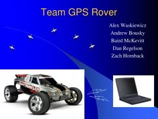
Team GPS Rover Critical Design Review. Alex Waskiewicz Andrew Bousky Baird McKevitt Dan Regelson Zach Hornback. Overview. Project Description Hardware Implementation Software Implementation Milestones Risks and Contingencies. PROJECT DESCRIPTION. Project Goals.

E N D
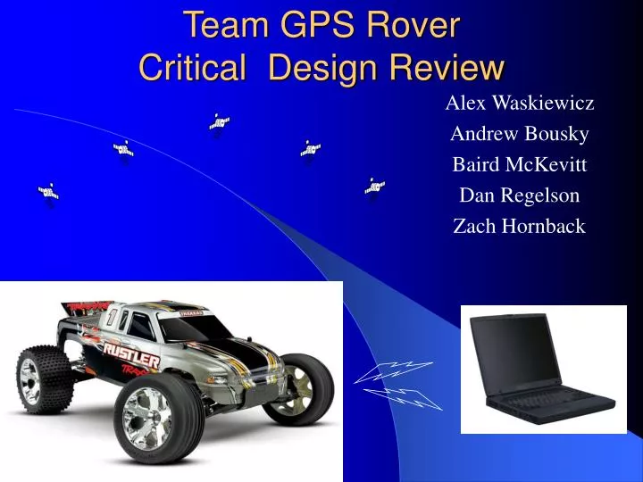
Team GPS RoverCritical Design Review Alex Waskiewicz Andrew Bousky Baird McKevitt Dan Regelson Zach Hornback
Overview • Project Description • Hardware Implementation • Software Implementation • Milestones • Risks and Contingencies
Project Goals • The human user will be able to remotely control the rover from a laptop computer • Direct driving control • Issue location commands • Rover will calculate its current bearing • Rover will calculate desired bearing to user specified location • Rover will autonomously maneuver to its assigned destination • Rover will transmit telemetry to the user • Rover will sense and avoid obstacles • Rover could have onboard camera(s) providing visual feedback to user. • Rover could carry and deploy instrumentation packages • Examples: • Rocket launch platform • Environmental sensors • Mechanical Manipulator
VEHICLE • Traxxas Rustler • 445x311x178 mm • 1.69 kg • Top Speed 35 mph • $203 with batteries • High Load Capacity • Replaceable parts • Electronics Platform • Attaches to the chassis • Carries electronics, sensors, and batteries • Interfaces directly with car controls • Weight and Size are constraints
Test: Steering and Driving • The steering and speed of the vehicle can be controlled using the PWMs of the microcontroller. • Both are controlled by altering the duty cycle of the input square wave. • The wave (for both steering and speed) has an amplitude of 4.2 Volts and a frequency of 49.75Hz • The duty cycles for steering are: • Straight – 7.72% • Full Left – 10.21% • Full Right – 5.37% • The duty cycles for driving are: • Idle – 7.46% • Full Forward – 9.95% • Full Reverse – 4.71 %
Hardware Block Diagram User PC GPS Module Digital Compass SCI Module SCI Module I2C Module Microcontroller PWM Module PWM Module Proximity Sensors Drive Motor Steering Motor
Test: GPS Parts • Serial communication OOB • Acquired outside signal • Impressive spatial resolution (probably to WAAS enable) • 1 Hz update rate • Documentation says modifiable and/or query-able but currently having technical difficulties
Digital Compass • $60 • ½ degree resolution • I2C interface • Testing will be imminent once I2C communication on the development board is established
Sensors • Two-forward facing sensors to allow obstacle avoidance • Ultrasonic: 2 x Devantech SRF08 Ranger ($62) • 6m range • I2C interface • Testing will be imminent once I2C communication on the development board is established
Development Board • Serial Ports • LCD • DIP Switches • LEDs • Shaft Encoder • Mini-Breadboard • Great for testing!
Power Subsystem • 3.3V, 5V systems • Need to pick battery • Use of 2 voltage regulators • Need to pick type • Will be implemented upon completion of PCB fabrication • Due to development board usefulness
Microcontroller: Freescale HCS08 • 60K of low-speed Flash • 4K of internal ram – Requires no external routing • Internal A/D • Internal PWM • 3.3V
Microcontroller: Freescale HCS08 Memory Map Internal module status/comm registers
Preliminary PCB Layout: US1 US2 GPS 4 4 6 • PCB: • Microcontroller • RF link • Voltage Regulators: Power Bus • Caps/Resistors V/R Power
Milestone #1 (Implementation Cycle 1) • User control with Arrow Keys • Serial Communication (tethered) • Independent PWM Control • Windows-based GUI • Why? • Tests many subsystems that are required for GPS Control (i.e. Milestone #2)
Milestone #2 (Implementation Cycle 2) • GPS Feedback • GPS communication • Digital Compass communication (IIC) • Bearing calculation
Implementation Cycle 3 • Obstacle Avoidance • Left and Right Sensors with minimal common FOV • Left and Right allows for an easy avoidance algorithm • Left sensor = high go Right • Right sensor = high go Left • Both = high requires long range detection to avoid
ANDREW BAIRD DAN ZACH ALEX • Windows XP GUI • Development board testing • Implement control software • GPS Module • Schematic & PCB layout • Chassis Fabrication • Power Sub-system • Ultrasonic Sensors • Digital compass • Documentation • Chassis Fabrication • Schematic and PCB layout • PWM interface • Power sub-system • GPS module • Implement control software • Development board testing
Updated Risks and Contingency • Parts availability and shipping times • We have purchased many of our discrete components • The car interface is electrically simple • Interfacing I2C components • Microcontroller RAM/Storage limitations • RF Link • Learning curve on design software (CodeWarrior & Altium) • Power Consumption